Gimbal control method, gimbal control system and gimbal device

a control method and gimbal technology, applied in the field of gimbal devices, can solve the problems of inability to popularize direct current brushless gimbals during the marketization process, low response time, and low cost requirement, and achieve the effect of reducing the requirement of users, smooth hand, and good follow-up

Active Publication Date: 2018-05-24
HAOXIANG ELECTRIC ENERGY KUNSHAN
View PDF6 Cites 4 Cited by
  • Summary
  • Abstract
  • Description
  • Claims
  • Application Information

AI Technical Summary

Benefits of technology

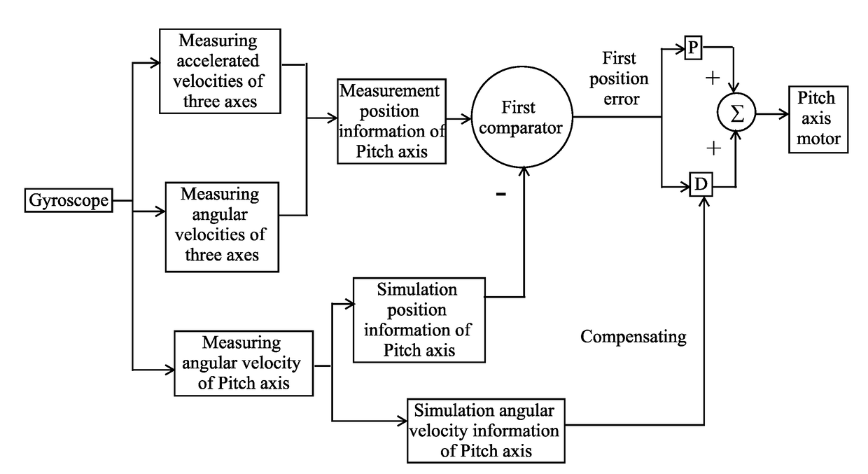
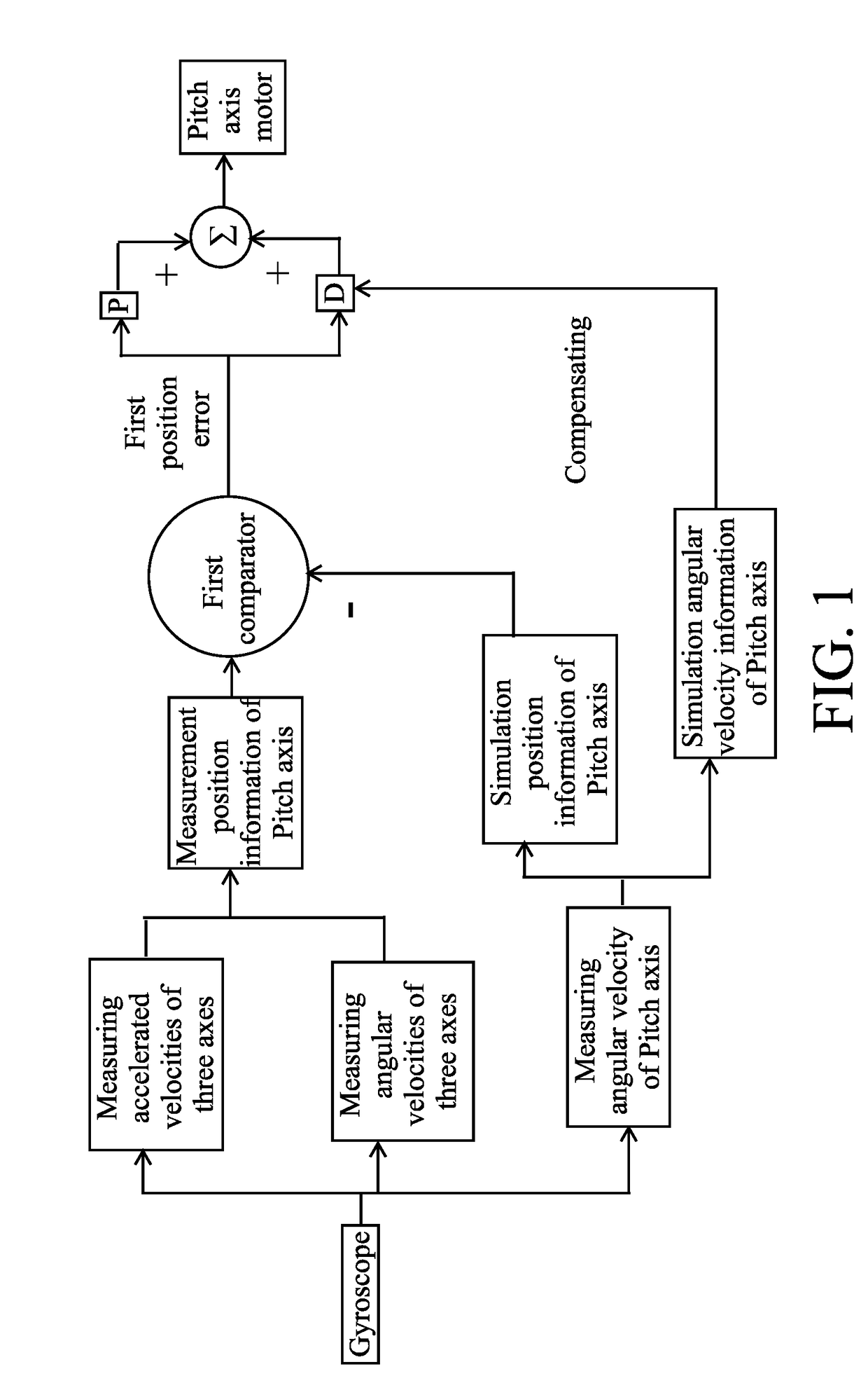
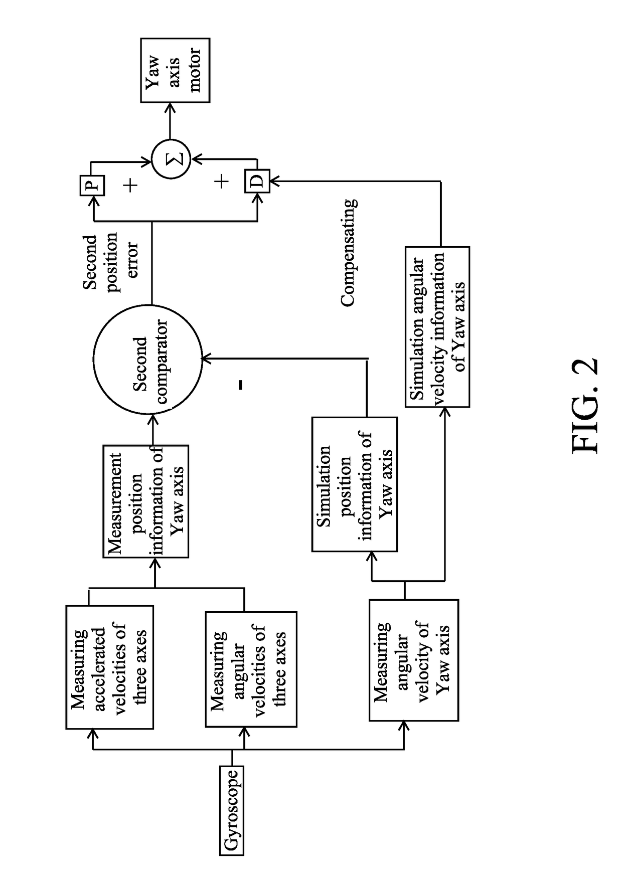
[0060]According to the gimbal control method, the gimbal control system and the gimbal device provided by the present invention, the direct current brush motor or the direct current brushless motor is adopted, so that the gimbal device has a smooth hand feeling during the process of manually adjusting the visual angle of the Pitch axis and/or the Yaw axis; moreover, the gimbal device has a good follow-up effect, so that the user can arbitrarily adjust the shooting visual angle of the gimbal device when shooting with the gimbal device provided by the present invention; and the gimbal device decreases a requirement of the user on the operation hand feeling. Under the premise that the Roll axis is kept horizontal, the gimbal device can further realize the omnidirectional attitude positioning and tracking control of the Pitch axis and the Yaw axis, especially the omnidirectional positioning and tracking shooting of the visual angle of the Pitch axis. Thus, the gimbal device pr...

Problems solved by technology

The direct current brushless gimbal has an advantage of low noise, but has a high cost, resulting in that the direct current brushless gimbal cannot be popularized during the marketization process.
When tracking, the brushless gimbal mainly tracks the heading angle, and the cost requirement thereof is relatively high.
Moreover, during the tracking shooting process, the response sometimes i...

Method used


Image

  • Gimbal control method, gimbal control system and gimbal device
  • Gimbal control method, gimbal control system and gimbal device
  • Gimbal control method, gimbal control system and gimbal device

Examples


Embodiment Construction

[0070]Features of various aspects and the preferred embodiment of the present invention are illustrated in detail as follows. Many specific details are provided in the following detailed description, for providing a comprehensive understanding of the present invention. For one skilled in the art, it is obvious that the present invention can be implemented with omitting some specific details. The following description of the preferred embodiment is merely for providing some examples of the present invention, so as to provide a better understanding of the present invention. In the description of the drawings and the preferred embodiment, the common structure and technology are not illustrated, so as to avoid a misunderstanding of the present invention. The same reference character in the drawings represents the same or similar structure, and thus the detailed description thereof is omitted. Moreover, the features, structures and characteristics which are descried below can be combined...


PUM


Abstract

A gimbal control method, a gimbal control system and a gimbal device are provided. The method includes steps of: obtaining simulation position information, measurement position information and simulation angular velocity information of a Pitch axis of a gimbal in real-time; calculating a first position error between the simulation position information of the Pitch axis and the measurement position information of the Pitch axis; processing the first position error with proportional-derivative calculation, wherein the first position error is compensated with the simulation angular velocity information during the proportional-derivative calculation; and, according to a result of the proportional-derivative calculation after compensating, generating a first torque control instruction for controlling a torque of a Pitch axis motor, so as to enable the Pitch axis to reach a position corresponding to the simulation position information of the Pitch axis. According to the present invention, a brush motor is adopted.

Description

CROSS REFERENCE OF RELATED APPLICATION[0001]The application claims priority under 35 U.S.C. 119(a-d) to CN 201710075508.1, filed Jan. 23, 2017.BACKGROUND OF THE PRESENT INVENTIONField of Invention[0002]The present invention relates to a technical field of gimbal device, and more particularly to a gimbal control method, a gimbal control system and a gimbal device.Description of Related Arts[0003]The available handheld gimbal in the market is mainly the direct current brushless gimbal. The direct current brushless gimbal has an advantage of low noise, but has a high cost, resulting in that the direct current brushless gimbal cannot be popularized during the marketization process.[0004]Conventionally, in the aspect of tracking shooting, the brushless gimbal mainly depends on the camera for automatically tracking shooting or shooting with the fixed visual angle. When tracking, the brushless gimbal mainly tracks the heading angle, and the cost requirement thereof is relatively high. More...

Claims


Application Information

Patent Timeline
IPC IPC(8): H04N5/232G03B17/56F16M13/04
CPCG03B17/561F16M13/04G02B27/646H04N5/2328G05D1/0094G05D1/08G05D3/203H04N23/66G02B27/644H04N23/685
Inventor TIAN, YUJIANG, WENYAN
Owner HAOXIANG ELECTRIC ENERGY KUNSHAN
Why Eureka
Try Eureka