Power equipment

a technology of power equipment and stoppers, which is applied in the direction of mowers, agriculture tools and machines, etc., can solve the problems of deformation or increase the size of the operation lever and/or the stopper, and reduce the design freedom of the operating portion including the operation lever, so as to prevent deformation and damage of the operation lever and/or the stopper, and increase the strength of the component parts. the effect of the strength

Active Publication Date: 2018-05-31
HONDA MOTOR CO LTD
View PDF0 Cites 3 Cited by
  • Summary
  • Abstract
  • Description
  • Claims
  • Application Information

AI Technical Summary

Benefits of technology

[0024]Thus, according to one aspect of the present invention, there is provided power equipment which can prevent deformation and damage of the operation lever and / or the stopper without increasing the strength of these component parts.

Problems solved by technology

If an external force (operation force) for rotating the operation lever relative to the handle beyond the prescribed rotation angle range is applied to the operation lever, an excessive load acts on the operation lever to cause deformation or damage to the operation lever and / or the stopper.
To prevent the operation lever and the stopper from suffering deformation or damage, it may be considered to increase the strength of these components, but the increase in the strength would lead to an increase in size of the operation lever and the stopper, which in turn would reduce the degree of design freedom of the operating portion including the operation lever.

Method used


Image

  • Power equipment
  • Power equipment
  • Power equipment

Examples


Embodiment Construction

)

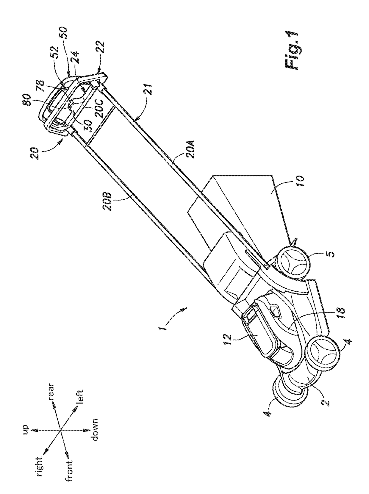
[0041]A walk behind electric lawn mower embodying power equipment according to the present invention will be described in the following with reference to FIGS. 1 to 14.

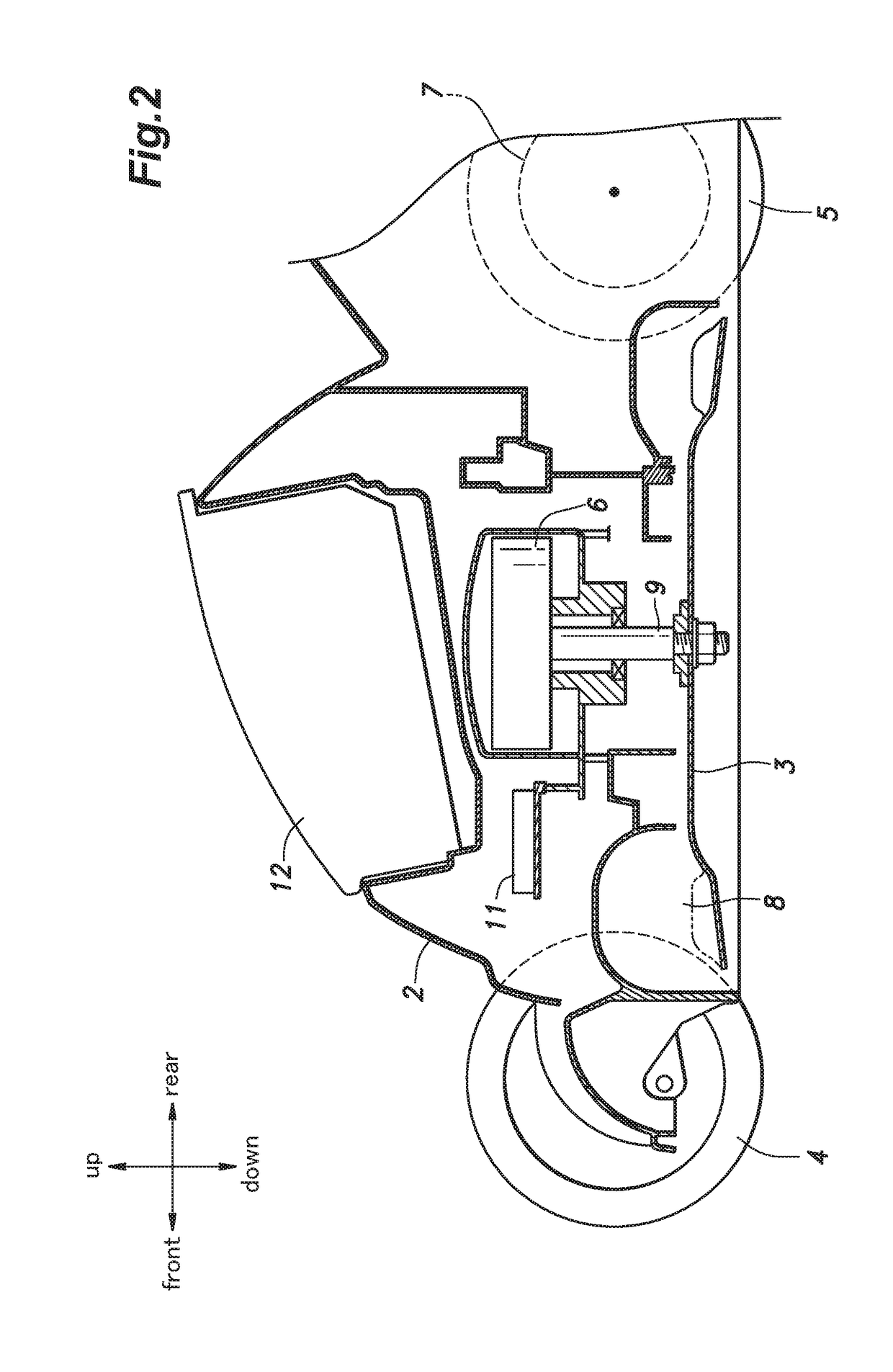
[0042]As shown in FIGS. 1 and 2, the electric lawn mower 1 includes a main body 2, a cutter blade 3 provided in the main body 2, a pair of front wheels 4 and a pair of rear wheels 5 each supported rotatably on the main body 2, a cutter blade electric motor (work unit electric motor) 6 provided in the main body 2 to drive the cutter blade 3, and a travel electric motor 7 for driving the rear wheels 5.

[0043]The cutter blade 3 is disposed in a cutter blade chamber 8 formed in a bottom of the main body 2 so as to open downward such that the cutter blade 3 is rotatable in a substantially horizontal plane. The cutter blade 3 is secured to a lower end of an output shaft 9 of the cutter blade electric motor 6 and is driven by the output shaft 9 to rotate about a vertical axis. A grass bag 10 is provided to a rear end of the ...


PUM


Abstract

In one aspect, power equipment includes a cutter blade operation lever, a left rotary shaft, an operated member operated by the left rotary shaft to control driving of a cutter blade, and a releasable engagement mechanism provided between the left rotary shaft and the cutter blade operation lever. The releasable engagement mechanism is configured to release a force transmitting engagement between the cutter blade operation lever and the left rotary shaft to allow the cutter blade operation lever to rotate relative to the left rotary shaft when an excessive force is applied to the cutter blade operation lever in a direction to rotate the left rotary shaft beyond a normal rotational angle range.

Description

TECHNICAL FIELD[0001]The present invention relates to power equipment, and particularly relates to power equipment, such as lawn mowers, tillers and snow blowers, having a work unit driven by a motor such as an electric motor or an internal combustion engine.BACKGROUND OF THE INVENTION[0002]Some electric lawn mowers has a main body provided with wheels, a mowing unit including a cutter blade, and an electric motor for driving the cutter blade, and further has a handle including a pair of side rod members extending rearward from the main body (see JPH02-055521U, US2013 / 0046448A1, and EP2875709A1, for example). In such an electric lawn mower, an operation lever is pivotably provided to the handle, such that an operation of the operation lever turns on / off an electric switch to thereby drive / stop the electric motor and hence the cutter blade.[0003]As the operation lever turns on / off the electric switch by being rotated relative to the handle by a prescribed rotation angle, the operatio...

Claims


Application Information

Patent Timeline
Patent Type & Authority Applications(United States)
IPC IPC(8): A01D34/00A01D69/02
CPCA01D34/006A01D69/02A01D2101/00A01B33/028A01D34/824A01D2034/6843
Inventor OOTA, YOSHITAKA
Owner HONDA MOTOR CO LTD
Why Eureka
Try Eureka