Tubular air cleaner for internal combustion engine and tubular filter element

a technology of internal combustion engine and filter element, which is applied in the direction of machine/engine, combustion-air/fuel-air treatment, and separation processes, etc., can solve the problems of increasing airflow resistance, and achieve the effect of reducing air pressure loss

Active Publication Date: 2018-05-31
TOYOTA BOSHOKU KK
View PDF5 Cites 6 Cited by
  • Summary
  • Abstract
  • Description
  • Claims
  • Application Information

AI Technical Summary

Benefits of technology

[0006]Therefore, there is room for improvement to reduce the air pressure loss.
[0007]It is an object of the present invention to provide a tubular air cleaner for an internal combustion engine and a tubular filter element that reduce air pressure loss.
[0010]With this structure, when air flows through the filter element into the inner side of the filter element, the air is allowed to reach the outlet without passing through the adsorbent filter. Thus, when air flows through the inner side of the filter element, an increase in the flow resistance caused by the adsorbent filter will be limited. Consequently, the air pressure loss is reduced.
[0012]Additionally, the adsorbent filter may be set to any position in the axial direction of the filter portion. This increases the degree of freedom for arranging the adsorbent filter.

Problems solved by technology

The filter element described in Japanese Laid-Open Patent Publication No. 2001-123897 has the drawback of increasing the airflow resistance.

Method used


Image

  • Tubular air cleaner for internal combustion engine and tubular filter element
  • Tubular air cleaner for internal combustion engine and tubular filter element
  • Tubular air cleaner for internal combustion engine and tubular filter element

Examples


modified examples

[0060]The above embodiment may be modified as follows.

[0061]The layer structure of the adsorbent filter 46 may be changed, for example, by omitting the glass fiber nets. The material forming the adsorbent layer only needs to adsorb evaporated fuel. Thus, an adsorbent differing from activated carbon such as zeolite may be used.

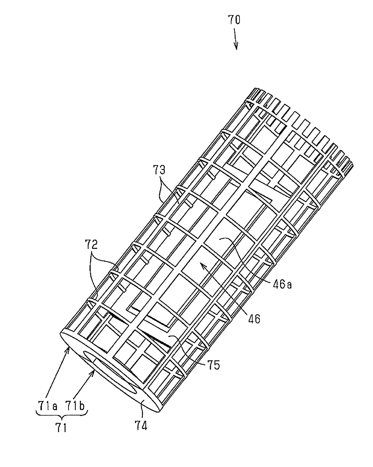
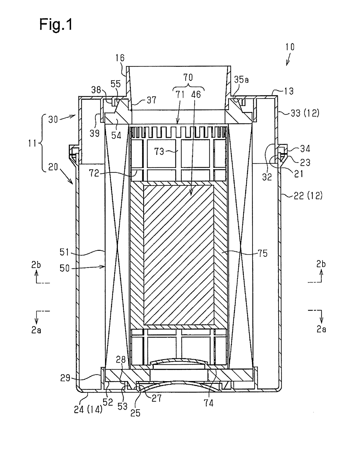
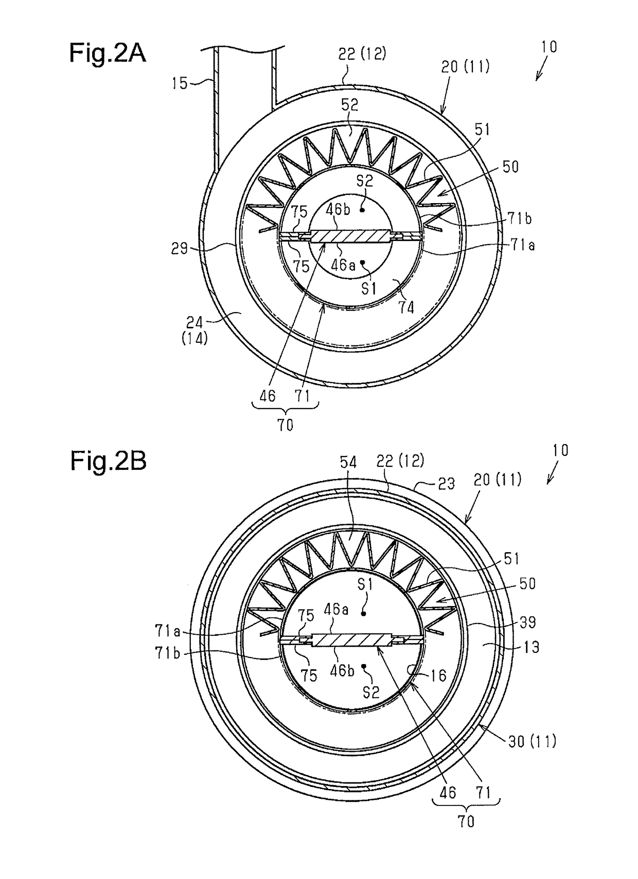
[0062]The adsorbent filter 46 may be arranged so as not to extend through the central axis of the filter element 50.

[0063]The adsorbent filter 46 may be inclined from the axial direction of the filter element 50.

[0064]The holding portions 75 may hold only one, two, or three sides of the four sides of the peripheral edge portion 47 of the adsorbent filter 46.

[0065]The shape of the adsorbent filter 46 may be changed from the rectangular plate to, for example, a trapezoidal plate.

[0066]When the framework 71 is molded from a resin, the adsorbent filter 46 may be inserted so that the framework 71 and the adsorbent filter 46 are formed integrally with each other. The...


PUM

PropertyMeasurementUnit
shapeaaaaaaaaaa
air pressure lossaaaaaaaaaa
flow resistanceaaaaaaaaaa

Abstract

A tubular air cleaner for an internal combustion engine includes a tubular housing, which includes a circumferential wall including an inlet, a top wall including an outlet, and a bottom wall opposed to the top wall, and a tubular filter element, which includes a tubular filter portion and is accommodated in the housing. A frame is arranged at an inner side of the filter portion to maintain shape of the filter portion. A planar adsorbent filter, which adsorbs evaporated fuel of the internal combustion engine, extends in an axial direction of the filter portion and is fixed to the frame. The inner surface of the filter portion is spaced apart from each of opposite planes of the adsorbent filter by a gap that allows air to reach the outlet without passing through the adsorbent filter.

Description

BACKGROUND ART[0001]The present invention relates to a tubular air cleaner arranged in an intake air passage of an internal combustion engine and a tubular filter element adapted for use with the tubular air cleaner.[0002]A prior art tubular air cleaner for an internal combustion engine includes a tubular housing and a tubular filter element. The housing includes a circumferential wall including an inlet, a top wall including an outlet, and a bottom wall opposed to the top wall. The filter element is accommodated in the housing.[0003]The tubular filter element includes a pleated tubular filter portion, which is formed by pleating a filter medium sheet, and two sealing portions, which are arranged on opposite ends of the filter portion in an axial direction to seal the space between the top wall and the bottom wall of the housing.[0004]Japanese Laid-Open Patent Publication No. 2001-123897 discloses a filter element that includes a filter portion and an inner tube, which is arranged a...

Claims


Application Information

Patent Timeline
Patent Type & Authority Applications(United States)
IPC IPC(8): F02M35/02F02M35/024F02M25/08B01D46/00B01D46/52B01D53/04
CPCF02M35/0201F02M35/02483F02M25/0854F02M25/089B01D46/0036B01D46/521B01D53/0407B01D2279/60B01D2253/102F02M35/02433F02M35/0245F02M35/042B01D46/2411B01D53/0415B01D2257/702B01D2259/4566
Inventor MORIKAWA, HIROAKI
Owner TOYOTA BOSHOKU KK
Why Eureka
Try Eureka