Method for Calculating an Optimised Trajectory

a trajectory and optimization technology, applied in the field of optimizing the trajectory, can solve the problems of cumbersome improvements to the trajectory, inability to introduce components into the press in a narrow region, and requiring experienced and qualified staff, so as to facilitate the influence of the method, improve the optimization trajectory, and strengthen the user's intuition

Active Publication Date: 2018-05-31
SIEMENS AG
View PDF0 Cites 5 Cited by
  • Summary
  • Abstract
  • Description
  • Claims
  • Application Information

AI Technical Summary

Benefits of technology

[0083]Advantageously, such a procedure facilitates influencing of the method for providing an optimized trajectory by an intuitively grasping and thinking user. Consequently, an experienced user is able to provide a stimulus in a direction of the optimization that the method for providing the optimized trajectory improves. At the same time, the user can strengthen their intuition for how a point-wise/region-wise modification of an optimized trajectory effects the course of the optimized trajectory.
[0084]Displaying a collision of the component with the production machine via colored markings in the regions of the production machine

Problems solved by technology

A problem that arises during the automated introduction of the component via of a holder, particularly in the case of presses, is that the component can

Method used


Image

  • Method for Calculating an Optimised Trajectory
  • Method for Calculating an Optimised Trajectory
  • Method for Calculating an Optimised Trajectory

Examples


Embodiment Construction

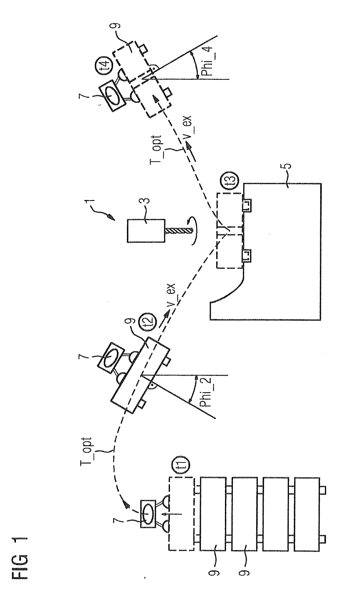
[0111]FIG. 1 shows a production machine 1, a component 9 and a trajectory T_opt. At time t1, the components 9 are received by the holder 7 and conveyed along the trajectory T_opt into the production machine 1. Here, the component 9 and the holder 7 move along the trajectory T_opt. At time t2, the component 9 is aligned in terms of its alignment Phi_2 with the aid of the holder. At time t2, the component 9 and the holder 7 have a speed v. The speed advantageously is a function of the time t and / or the position or alignment Phi of the component. The component 9 is inserted into the production machine 1, in particular into the lower tool 5 of the production machine 1, by the holder 7. In the production machine 1, the component 9 is processed by the upper tool 3. Here, a drill 3 or a part of a milling machine 3 serves as upper tool 3. After the processing in the production machine 1, the holder 7 re-receives the component 9 at the time t3 and guides the component 9 out of the production...


PUM


Abstract

A method for calculating an optimized trajectory via a simulation program and an optimization routine, wherein the trajectory is provided via the simulation program and adapted to boundary conditions, where the method includes a loop in which, as individual steps, a first trajectory is provided, a further trajectory, and the adaptation of the further trajectory is modified based on the boundary conditions, such that the optimized trajectory is a trajectory which has been provided based on an extremal or predetermined parameter, where the optimized trajectory is provided after the calculation by a control device for moving a holder for a component, and where at least one component and the production machine are displayed in a 3D display.

Description

CROSS-REFERENCE TO RELATED APPLICATIONS[0001]This is a U.S. national stage of application No. PCT / EP2016 / 062378 filed 1 Jun. 2016 and claims the priority of European application No. 15170497.0 filed Jun. 3, 2015, the content of which is incorporated herein by reference in its entirety.BACKGROUND OF THE INVENTION1. Field of the Invention[0002]The invention relates to a method for calculating an optimized to trajectory of a component, a computer program package for implementing the method, a control apparatus that performs the method and to a production machine, in particular a press, having such a controller.2. Description of the Related Art[0003]Presses are used in multifarious ways in industrial manufacturing for processing components, in particular sheets, for example, for producing body parts in the automotive industry. Production machines, in particular presses, are usually equipped in an automated manner. The production machine is equipped with a component by way of a holder, w...

Claims


Application Information

Patent Timeline
IPC IPC(8): G05B19/4069G05B19/418
CPCG05B19/4069G05B19/41885G05B2219/32014G05B2219/45142G05B2219/35009Y02P90/02
Inventor BONAY, ALEXANDREHOJA, STEPHANKNOCHE, FRANKMEIER, MICHAELLORENZ, ULRICH WOLFGANGSCHAEUFELE, STEPHAN
Owner SIEMENS AG
Why Eureka
Try Eureka