
Method for the manufacture of a plastic component, plastic component, and shoe

a technology of plastic components and manufacturing methods, applied in the field of plastic components, can solve the problems of delay in stabilization and cooling of the fused component, major share of steam energy lost in the mold, and limited shapes of the components that may be manufactured

Active Publication Date: 2018-06-07
ADIDAS
View PDF6 Cites 111 Cited by
  • Summary
  • Abstract
  • Description
  • Claims
  • Application Information

AI Technical Summary

Benefits of technology

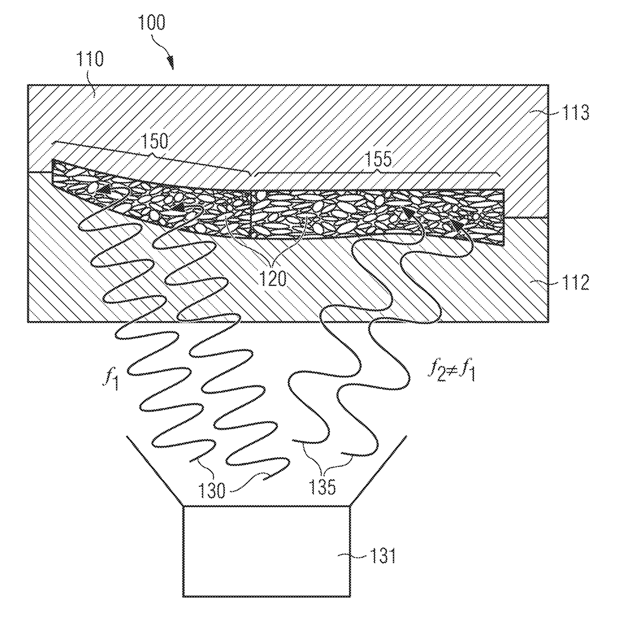
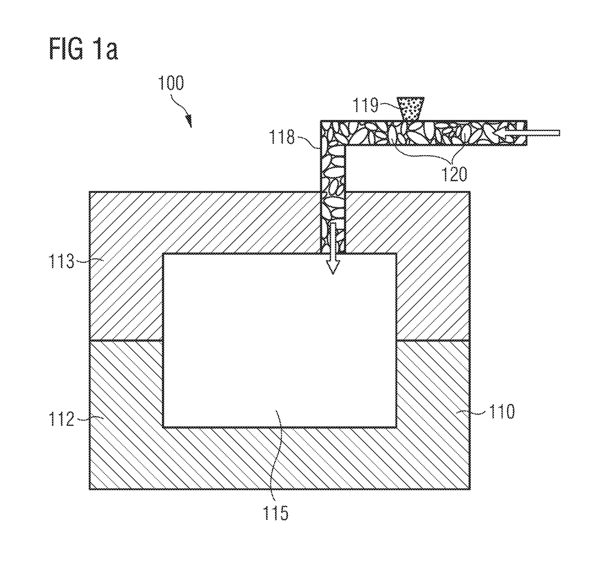
The present method described in this patent is beneficial because the mold only needs to absorb a limited amount of energy compared to the first material with the particles. This is achieved by using epoxy resin to manufacture the mold, which has complexly shaped cavities and low absorption power with respect to electromagnetic fields. Other methods known in the art can also be used to create molds with low absorption capabilities.

Problems solved by technology

Common to the methods known is, however, that the processing of the base material to dimensionally stable components of a high quality is often only possible up to a certain thickness or a certain packing density, meaning that the possible shapes of components that may be manufactured may be limited.
For a liquid binder material or heat energy supplied by steam, this is only possible to a limited degree for thicker components and / or may lead to imperfections, because “channels” or “inlet openings” are provided in the component to allow the binder or the steam to homogeneously infuse the base material within the mold.
Moreover, in particular when using steam as an energy carrier, it turns out to be undesirable that a major share of the energy stored within the steam may be lost in the mold instead of being supplied to the particles / particle surfaces.
This may, on the one hand, necessitate a long preheating phase until the mold is heated up to a saturation temperature, and may, on the other hand, delay stabilization and cooling of the fused component since the mold may have stored a large amount of heat energy that delays cooling.
Therefore, the method may be protracted and very energy inefficient.

Method used


Image

  • Method for the manufacture of a plastic component, plastic component, and shoe
  • Method for the manufacture of a plastic component, plastic component, and shoe
  • Method for the manufacture of a plastic component, plastic component, and shoe

Examples


embodiment 3

[0245]4. Method according to the preceding embodiment 3, wherein the particles are provided with the energy absorbing material prior to the loading of the mold.

[0246]5. Method according to any one of the preceding embodiments 3-4, wherein the energy absorbing material comprises water.

[0247]6. Method according to any one of the preceding embodiments 3-5, wherein the energy absorbing material comprises a metal.

[0248]7. Method according to any one of the preceding embodiments 1-6, wherein the energy is supplied in the form of radiation in the microwave range, 300 MHz-300 GHz.

[0249]8. Method according to any one of the preceding embodiments 1-7, wherein the energy is supplied in the form of radiation in the radio frequency range, 30 kHz-300 MHz.

[0250]9. Method according to any one of the preceding embodiments 1-8, wherein the energy is supplied by electromagnetic induction.

[0251]10. Method according to any one of the preceding embodiments 1-9, wherein more energy is supplied to the part...

embodiment 17

[0259]18. Shoe, in particular sports shoe, with a cushioning element according to

embodiment 18

[0260]19. Shoe , wherein the shoe is a running shoe.


PUM

PropertyMeasurementUnit
Volumeaaaaaaaaaa
Mechanical propertiesaaaaaaaaaa
Distanceaaaaaaaaaa

Abstract

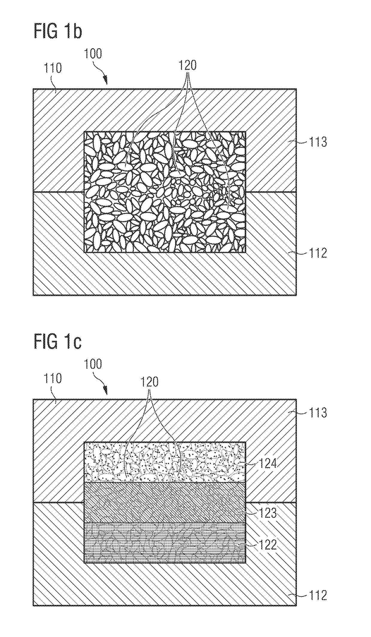
Described are methods for the manufacture of a plastic component, in particular a cushioning element for sports apparel, a plastic component manufactured with such a method, for example a sole or a part of a sole for a shoe, and a shoe with such a sole. According to an aspect of the invention, a method for the manufacture of a plastic component, in particular a cushioning element for sports apparel, is provided which includes loading a mold with a first material which includes particles of an expanded material, and, during loading the mold, pre-heating the particles by supplying energy, wherein the energy is supplied in the form of at least one electromagnetic field.

Description

CROSS REFERENCE TO RELATED APPLICATION[0001]This application is related to and claims priority benefits from German Patent Application No. DE 10 2016 223 980.5, filed on Dec. 1, 2016, entitled METHOD FOR THE MANUFACTURE OF A PLASTIC COMPONENT, PLASTIC COMPONENT, AND SHOE (“the '980.5 application”). The '980.5 application is hereby incorporated herein in its entirety by this reference.FIELD OF THE INVENTION[0002]The present invention relates to a method for the manufacture of a plastic component, in particular a cushioning element for sports apparel, a plastic component manufactured with such a method, for example a sole or part of a sole for a shoe, as well as a shoe with such a sole.BACKGROUND[0003]Nowadays, plastic components play an essential role in many areas of technology and everyday life. As examples, the aviation and aerospace industry as well as the automotive industry are mentioned. In these areas, plastic components may, for example, serve as impact protection elements, ...

Claims


Application Information

Patent Timeline
IPC IPC(8): B29D35/14B29D35/00
CPCB29D35/142B29D35/0063B29D35/148B29C44/02B29C44/3415B29C44/445B29L2031/504B29K2995/0082B29K2995/0063B29K2995/0094B29K2105/048B29C35/0805B29C43/02B29K2067/003B29K2067/006B29K2067/046B29K2075/00B29K2077/00B29C67/205B29C44/585B29C2035/0822B29C2035/0827B29C2035/0855B29C2035/0861B29K2101/12B29K2105/0005B29K2105/002A43B13/125A43B13/187B29C44/3426B29C44/0446A43B13/04B29D35/0054B29D35/122
Inventor KURTZ, MAXIMILIAN PHILIPPROMANOV, VICTORREUBER, NORBERTLE, TRU HUU MINHSEEFRIED, ANDREAS JOHANNESROBERTSON, CHRISTOPHERHOLMES, CHRISTOPHER EDWARDFATHI, AMIR
Owner ADIDAS
Learn More