Eureka AIR delivers breakthrough ideas for toughest innovation challenges, trusted by R&D personnel around the world.

Control device for supercharging system

a control device and supercharging technology, applied in the direction of electric control, machines/engines, combustion engines, etc., can solve the problems of affecting the device is broken, and the supercharger may transiently enter an abnormal operation state called surging, etc., to achieve the effect of maximizing the performance of the supercharger

Active Publication Date: 2018-06-07
MITSUBISHI HEAVY IND ENGINE & TURBOCHARGER LTD
View PDF0 Cites 1 Cited by
  • Summary
  • Abstract
  • Description
  • Claims
  • Application Information

AI Technical Summary

Benefits of technology

The patent text describes a control system for a supercharging system that can accurately move the supercharger to a specific position on a compressor map. This means that the supercharger can perform at its best level of performance.

Problems solved by technology

When the operational state of an engine changes suddenly, for instance, a supercharger may transiently enter an abnormal operation state called surging.
When a supercharger enters a surging state, it is no longer possible to compress intake air.
Further, if a supercharger enters a surging state often, it may lead to breakage of the devices.

Method used


Image

  • Control device for supercharging system
  • Control device for supercharging system
  • Control device for supercharging system

Examples


first embodiment

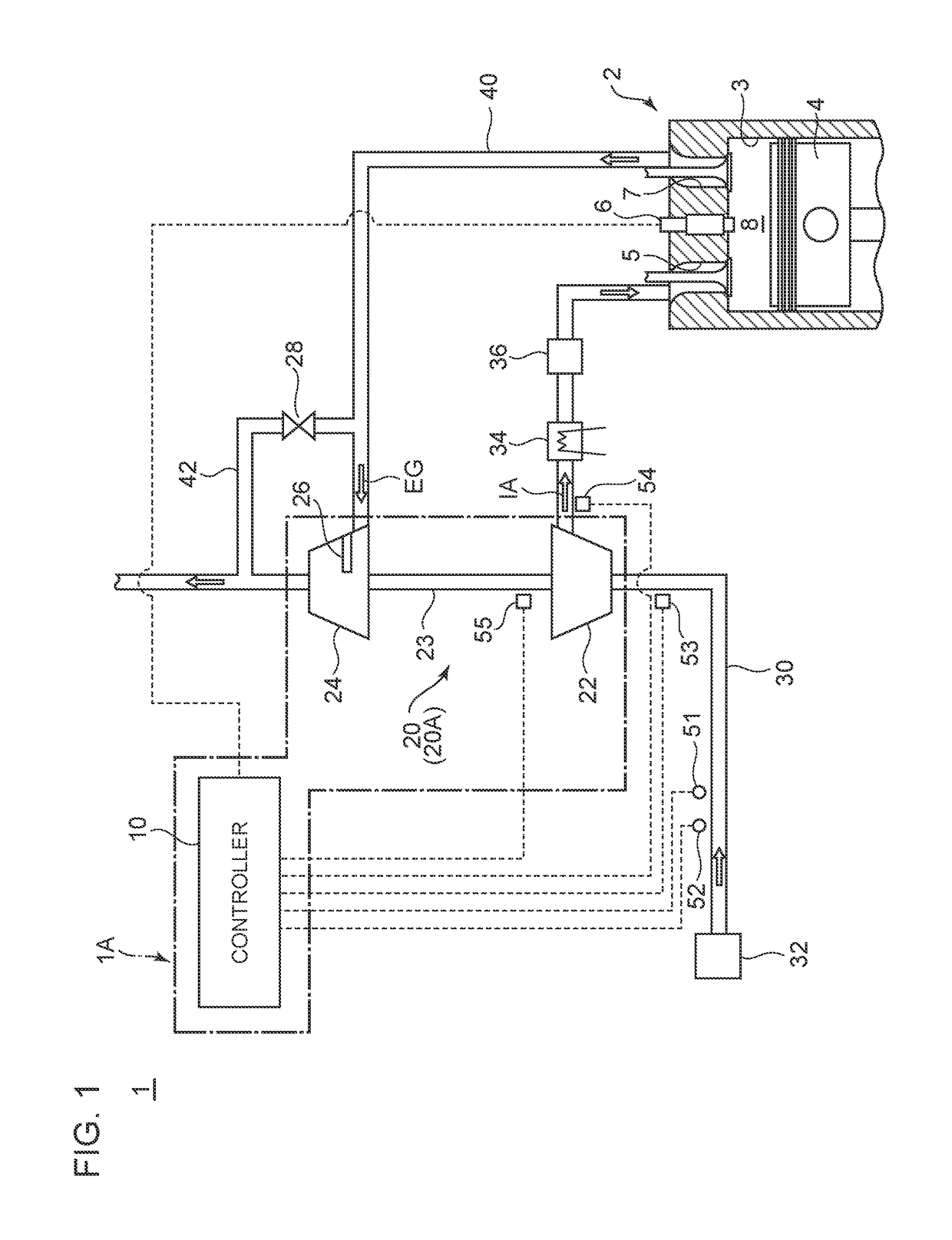
[0049]FIG. 1 is an overall configuration diagram of a supercharging system to which a control apparatus of a supercharging system according to an embodiment of the present invention is to be applied. A control apparatus 1A of a supercharging system according to an embodiment of the present invention is a control apparatus 1A of a supercharging system for supplying an engine 2 with compressed intake air IA, and as shown in FIG. 1, the control apparatus 1A includes a supercharger 20 including a compressor 22 to compress intake air IA to be supplied to the engine 2 and a controller 10 for controlling control devices that affect operation of the compressor 22.

[0050]In the depicted embodiment, the supercharger 20 includes a turbocharger 20A to rotate the compressor 22 with a turbine 24 which is rotated by exhaust gas EG discharged from the engine 2.

[0051]In the supercharging system 1 depicted in FIG. 1, air (intake air) introduced into an intake duct 30 via an air cleaner 32 flows into t...

second embodiment

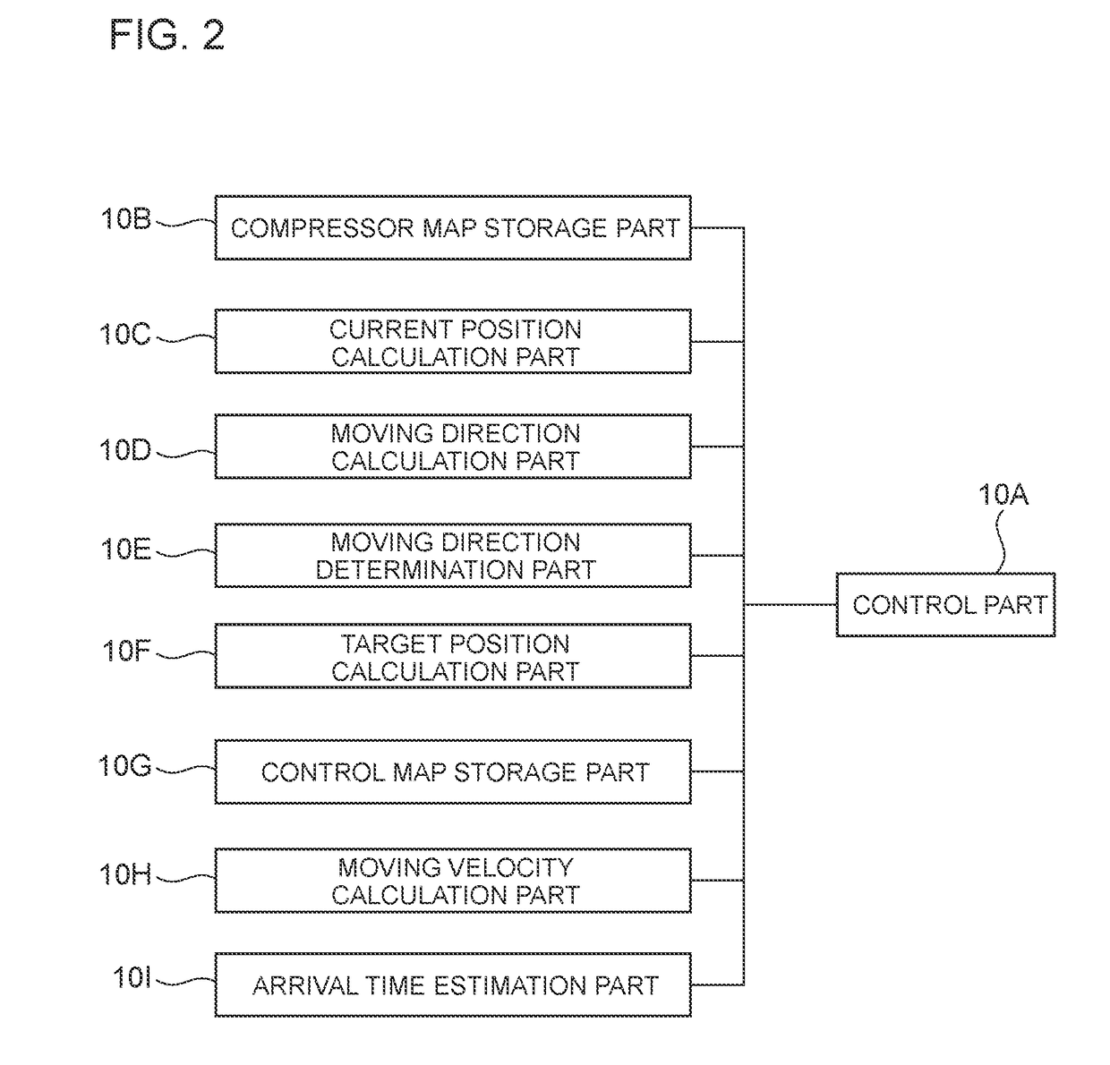
[0081]In some embodiments, as shown in FIG. 2, the controller 10 further includes a moving velocity calculation part 10H. The moving velocity calculation part 10H is a part of the controller 10, which has a function to calculate the moving velocity of the operational point 61, on the basis of the change amount per time of the current position of the operational point 61 calculated by the current position calculation part 10C.

[0082]As described below with reference to FIGS. 7 and 8, the control part 10A is configured to control the control devices 6, 26, 28 and the like on the basis of the current position of the operational point 61 calculated by the current position calculation part 10C, the moving direction of the operational point 61 calculated by the moving direction calculation part 10D, and the moving velocity of the operational point 61 calculated by the moving velocity calculation part 10H.

[0083]With this embodiment, the compressor 22 is controlled on the basis of the moving...

third embodiment

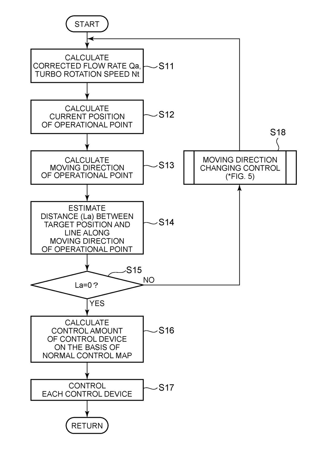
[0098]In some embodiments, as described below with reference to FIGS. 10 and 11, the control part 10A is configured to control the control devices 6, 26, 28 or the like so that the operational point 61 arrives at the target position in a shorter time than the second predetermined time td if the arrival time tb the operational point 61 takes to arrive at the target position from the current position is shorter than the second predetermined time td.

[0099]According to this embodiment, the compressor 22 is controlled so that the operational point 61 arrives at the target position in a shorter time than the second predetermined time td if the arrival time the operational point 61 takes to arrive at the target position from the current position is shorter than the second predetermined time td. This target position is a position where the compressor efficiency η is higher than a predetermined efficiency on the compressor map M1 (for instance, a position where the compressor efficiency η is...


PUM


Abstract

A control apparatus of a supercharging system for supplying an engine with compressed intake air, includes: a supercharger including a compressor configured to compress the intake air to be supplied to the engine; and a controller for controlling a control device affecting operation of the compressor. The controller includes: a compressor map storage part configured to store a compressor map which indicates a relationship of an intake volume flow rate, a pressure ratio, and a compressor rotation speed in the compressor; a current position calculation part configured to calculate a current position of an operational point of the compressor on the compressor map every predetermined period; a moving direction calculation part configured to calculate a moving direction of the operational point on the compressor map on the basis of the current position of the operational point calculated by the current position calculation part; and a control part configured to control the control device on the basis of the current position of the operational point calculated by the current position calculation part and the moving direction of the operational point calculated by the moving direction calculation part.

Description

TECHNICAL FIELD[0001]The present disclosure relates to a control device for a supercharging system for supplying an engine with compressed intake air.BACKGROUND ART[0002]As a technique to improve an output of an engine, a method (supercharging) of compressing intake air with a supercharger and supplying an engine with the compressed intake air is known, and widely used in various engines. When the operational state of an engine changes suddenly, for instance, a supercharger may transiently enter an abnormal operation state called surging. When a supercharger enters a surging state, it is no longer possible to compress intake air. Further, if a supercharger enters a surging state often, it may lead to breakage of the devices. Thus, a supercharger needs to be controlled appropriately so as to avoid entering a surging state as much as possible.[0003]Typically, as a technique to control a supercharger, a feedback control is performed on a supercharger so that an operational point on a c...

Claims


Application Information

Patent Timeline
IPC IPC(8): F02D41/00F02B37/22F02B37/18
CPCF02D41/0007F02B37/22F02B37/18F02D41/3005F02D45/00F02D23/00F02D23/02F02B2037/125F02D41/1406F02B2037/122F02B37/24Y02T10/12
Inventor TAKAHASHI, TOMOHIROIKEDA, TAKASHITERAKADO, KIYOSHIMORI, NAOYUKIJIWARIYAVEJ, VISSUTA
Owner MITSUBISHI HEAVY IND ENGINE & TURBOCHARGER LTD
Why Eureka
Eureka Blog
Learn More