
Micro-Standoff for Blind Holes

a technology of micro-standoff and blind hole, which is applied in the direction of threaded fasteners, sheet joining, fastening means, etc., can solve the problems of inefficiency of prior art, inability to meet the challenges of micro-components, and difficulty in searching for extra grip areas for mechanical bonding or even totally different means of attachment, etc., to achieve the effect of reducing the compressive for

Inactive Publication Date: 2018-06-07
PENN ENG & MFG CORP
View PDF0 Cites 1 Cited by
  • Summary
  • Abstract
  • Description
  • Claims
  • Application Information

AI Technical Summary

Benefits of technology

The present invention provides a fastener and method of installation that can rigidly attach to very thin panels with a cosmetically acceptable appearance. The fastener is a standoff fastener that uses a radial clinch process to minimize the compressive force applied to the receiving panel. The fastener can be attached without a reveal or witness mark on the opposite side. The connection is secure and the fastener is easy to install. The invention also includes a method of rigidly affixing the fastener to the panel using a punch and an anvil. The technical effects of the invention include a fastener that can securely attach to thin panels, a method of installation that is efficient and secure, and a connection that is visually acceptable.

Problems solved by technology

Since performance is highly affected and proportional to how much grip surface is available, this fastening mechanism approaches its limits in micro-assemblies where wall heights are very small, such as on the order of fractions of a millimeter, e.g. 0.2 mm in a 0.5 mm total substrate thickness with blind mounting holes of approximately 1 mm in diameter.
On this small scale, contact with side wall is not enough, and the search for extra grip areas for mechanical bonding or even for totally different means of attachment is challenging but highly needed.
In order to achieve the required push out and torque out resistances of a standoff, the prior art discloses relatively expensive means that are sometimes inefficient and inadequate to meet the challenges of micro-components.
This is an inadequate solution for blind holes and single-sided access panels.
During this process, a large amount if substrate material is wasted.
This process is time-consuming, inefficient and expensive.
In addition, the standoff and substrate panel material are the same, which may be inconvenient when thermal or electrical insulation is needed.
Adhesives are another inefficient and expensive way to attach the micro-standoff to the substrate.
The messy appearance and the uncontrolled thickness of an adhesive are major disadvantages.
Light curing and curing time also add to the undesirability of this approach.
Furthermore, this process is expensive since high current is involved, and is most often inefficient for ultra-thin substrates where cosmetic appearance is of critical importance.

Method used


Image

  • Micro-Standoff for Blind Holes
  • Micro-Standoff for Blind Holes
  • Micro-Standoff for Blind Holes

Examples


Embodiment Construction

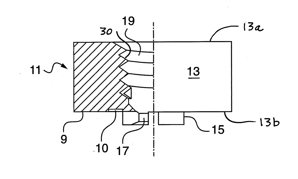
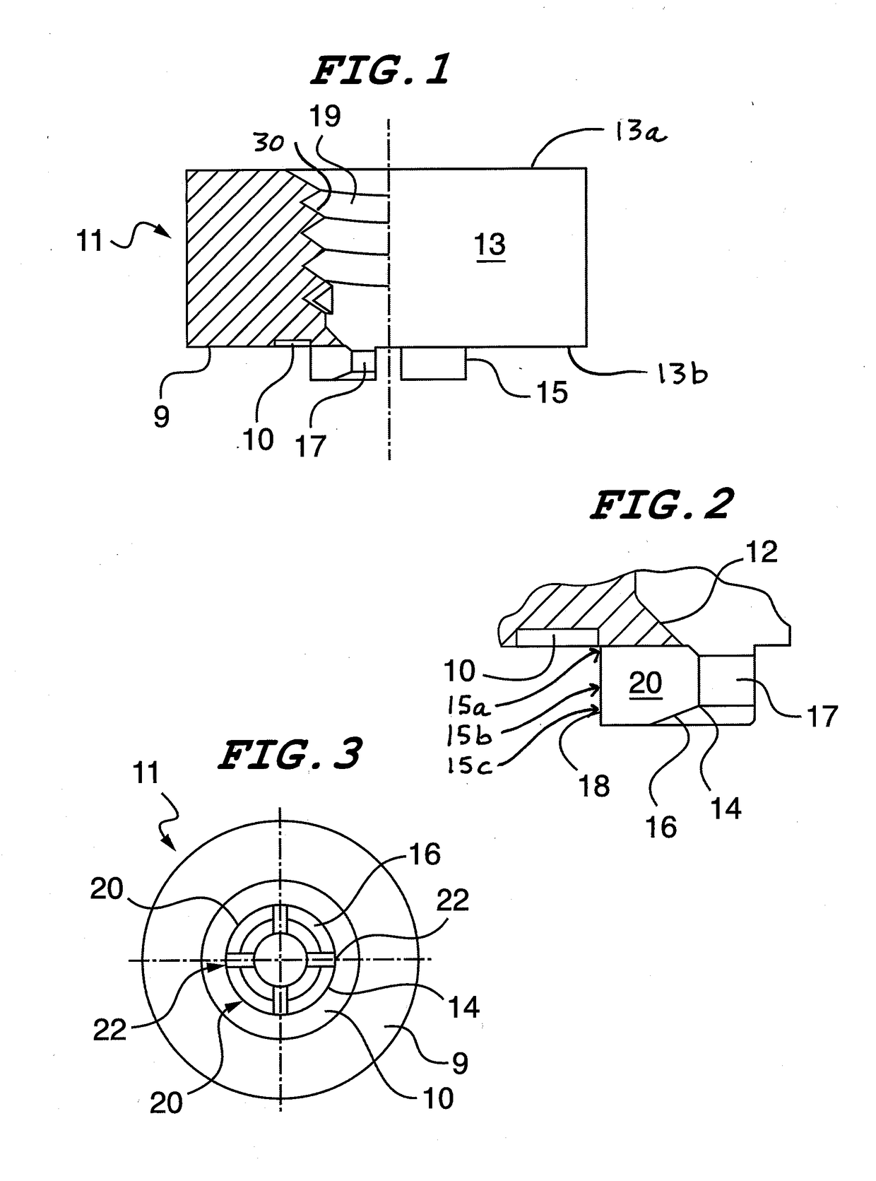
[0022]An internally-threaded standoff fastener in accordance with a preferred embodiment of the invention is shown in FIGS. 1-3 and is designated generally by reference numeral 11. Referring to FIG. 1, the fastener 11 is shown in partial section along a central axis of symmetry. The fastener 11 has a substantially-cylindrical body 13 with upper 13a and lower 13b axial ends. A central, threaded bore 19 extends axially through the body 13. The threads 30 of the bore extend from the upper end 13a to a location proximate the lower end 13b. An outer peripheral shoulder 9 is formed on the lower axial end 13b. The shoulder encircles the shank 15 as described below.

[0023]A short shank 15 extends axially from the lower end 13b of the body 13. Proceeding axially from the upper to the lower end, the shank has an upper 15a, central 15b and lower portion 15c. The shank 15 has a central internal bore 17 that is preferably co-axial with the internal, threaded bore 19 of the body 13. The central po...


PUM


Abstract

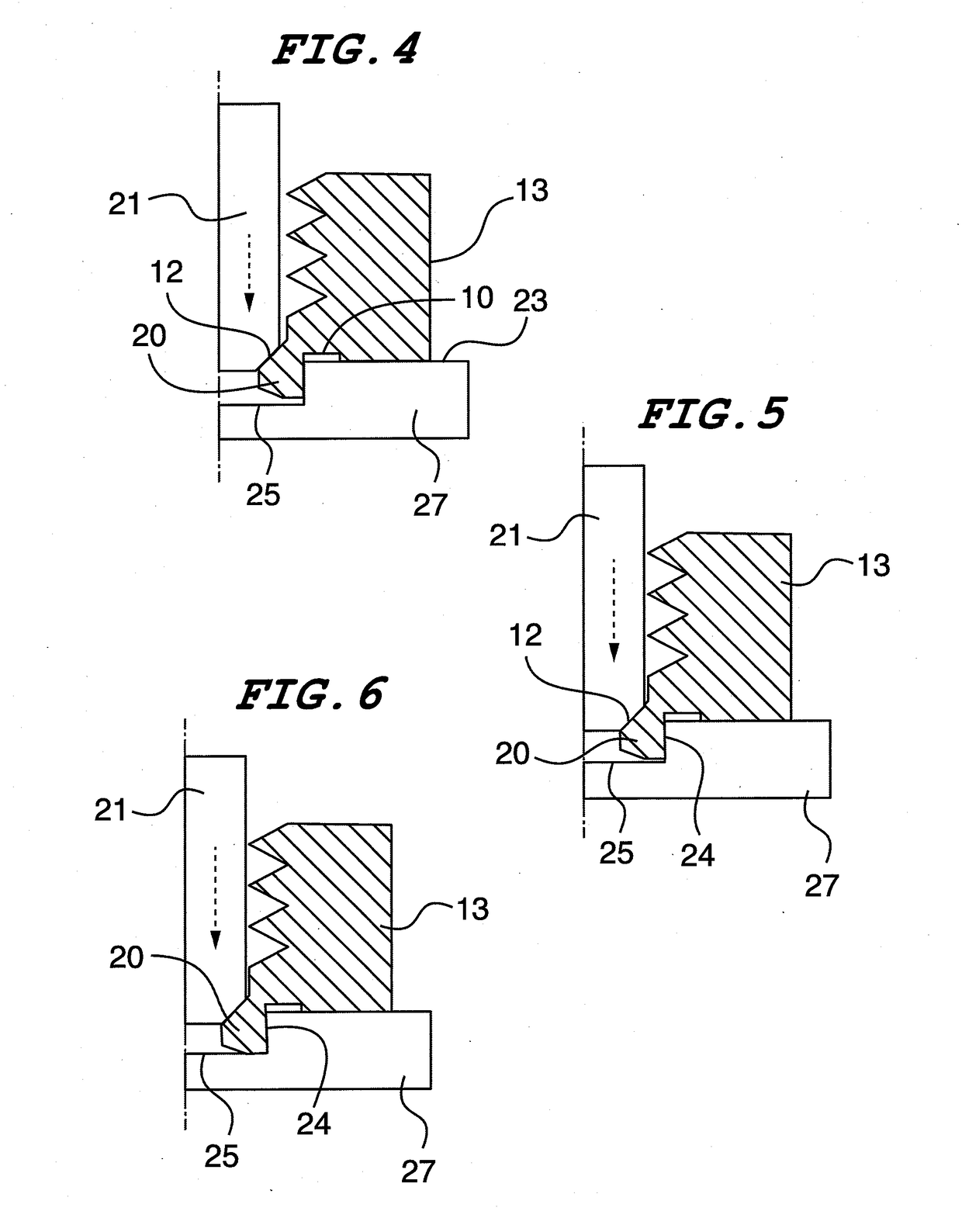
A standoff fastener for attaching to a blind hole in a metal panel. The fastener has a substantially cylindrical body with a short shank that extends downwardly from the body into the hole. The shank has an inwardly extending collar with a first inwardly facing chamfer on the top and a second outwardly facing chamfer located on the bottom. The body has a shoulder at the bottom with a circular recess adjacent to and encircling the shank. The shank is radially divided into four equal segments which are separated by four radial slots. When the shank is spread outwardly by a center installation punch pressing against the first chamfer, the outer distal edge of the shank is pressed into the side wall of the hole, while an edge at the top of the second chamfer embeds into the end wall of the hole.

Description

RELATED APPLICATIONS[0001]This is a non-provisional patent application based upon provisional patent application 62 / 430,830 filed Dec. 6, 2016 entitled, “Micro-Standoff for Blind Holes”, which is incorporated herein by reference and priority from which is hereby claimed.FIELD OF THE INVENTION[0002]The present invention relates to an internally-threaded fastener that rigidly attaches to a blind hole of a metal substrate. More particularly, the invention relates to fastener with projecting barbs that flare outwardly normal to the fastener's axis of symmetry into the side walls of the mounting hole.BACKGROUND OF THE INVENTION[0003]There are many known fasteners that have a shank that expands within and deforms the sidewalls of an unthreaded hole to form a firm grip. Since performance is highly affected and proportional to how much grip surface is available, this fastening mechanism approaches its limits in micro-assemblies where wall heights are very small, such as on the order of frac...

Claims


Application Information

Patent Timeline
Patent Type & Authority Applications(United States)
IPC IPC(8): F16B37/06F16B5/02
CPCF16B37/067F16B5/02F16B37/065
Inventor ABBOUD, JACQUES
Owner PENN ENG & MFG CORP
Learn More