
Ergonomic hand tools, construction thereof, and packaging therefor

Inactive Publication Date: 2005-10-13
BAKER BRUCE
View PDF68 Cites 4 Cited by
  • Summary
  • Abstract
  • Description
  • Claims
  • Application Information

AI Technical Summary

Benefits of technology

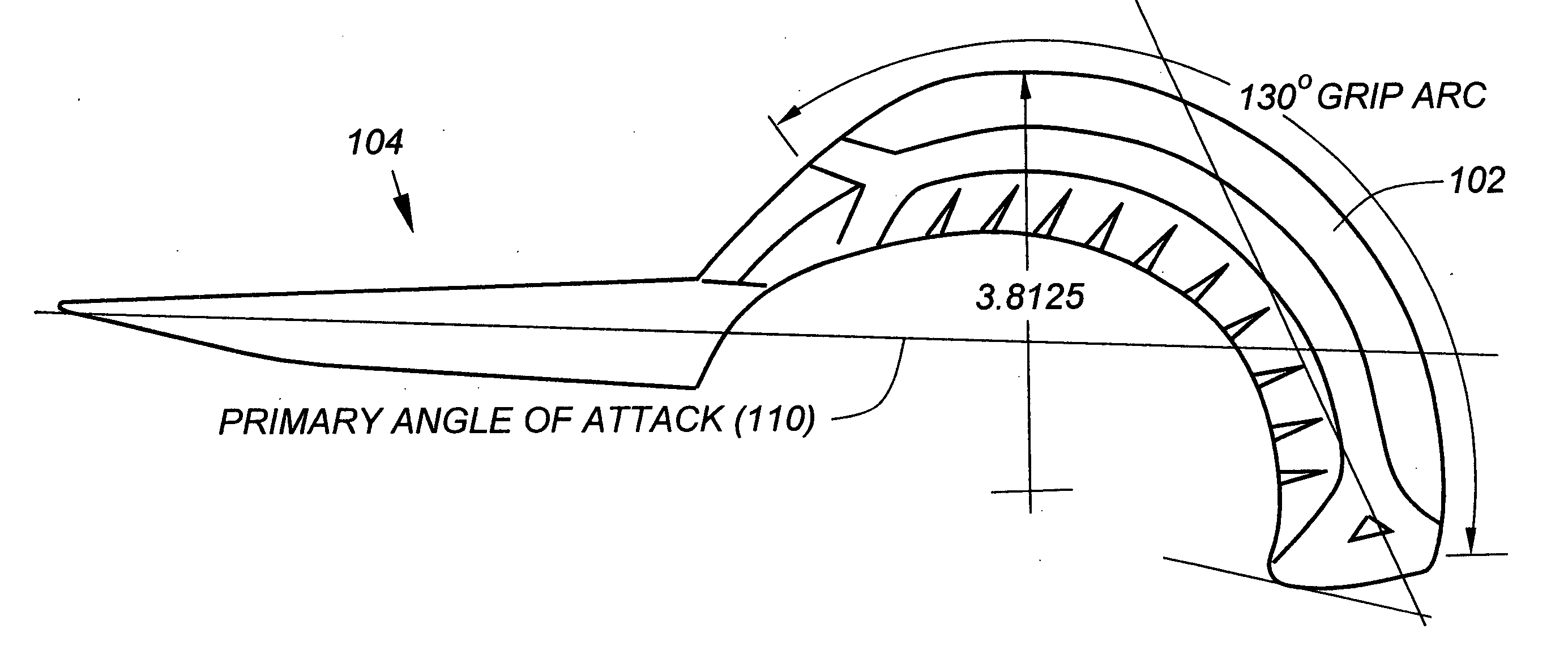
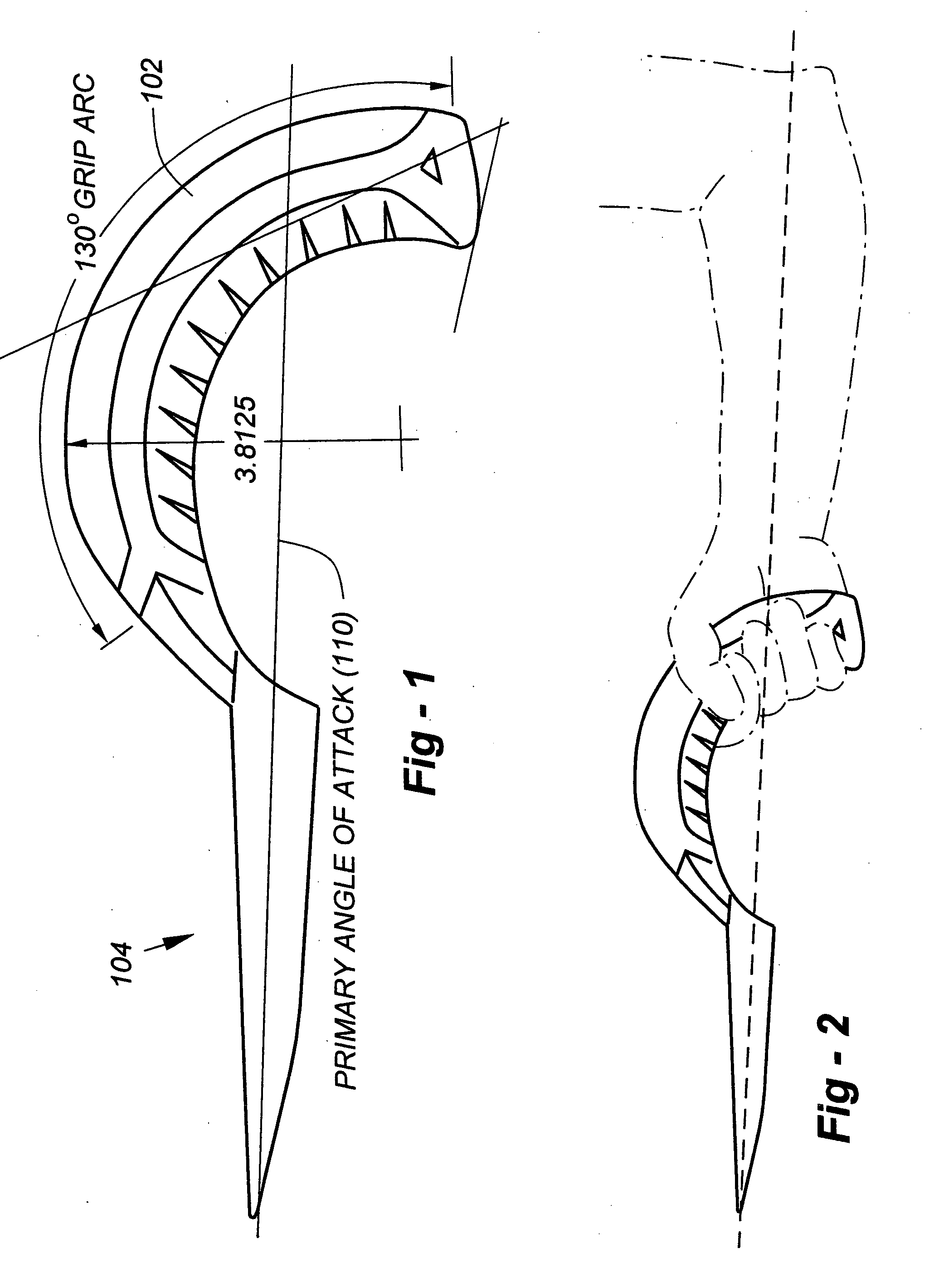
[0009] This invention addresses the natural arc of attack and motion associated with hand tool design by providing a methodology for implementing an ergonomic hand grip for tools, implements or other utensils. The invention broadly facilitates the use by a hand of such tools, implements or other utensils within their arc of natural use, motion and attack without requiring extension, flexion, radial deviation, or ulnar deviation of the wrist from the neutral plane of the forearm.
[0010] The preferred embodiments further include a grip shaped to increase the effectiveness of the tool and minimize antagonism between muscles and tendons of the wrist, forearm and upper arm, while maximizing the effectiveness of the gripping force delivered to it by the user. Maintaining the wrist and forearm in a neutral position increases a tool user's potential strength by increasing the synergy between large muscles of the forearm and upper arm and shoulders. It also decreases compression of the tendons and nerves in the carpal tunnel and between the wrist and forearm.
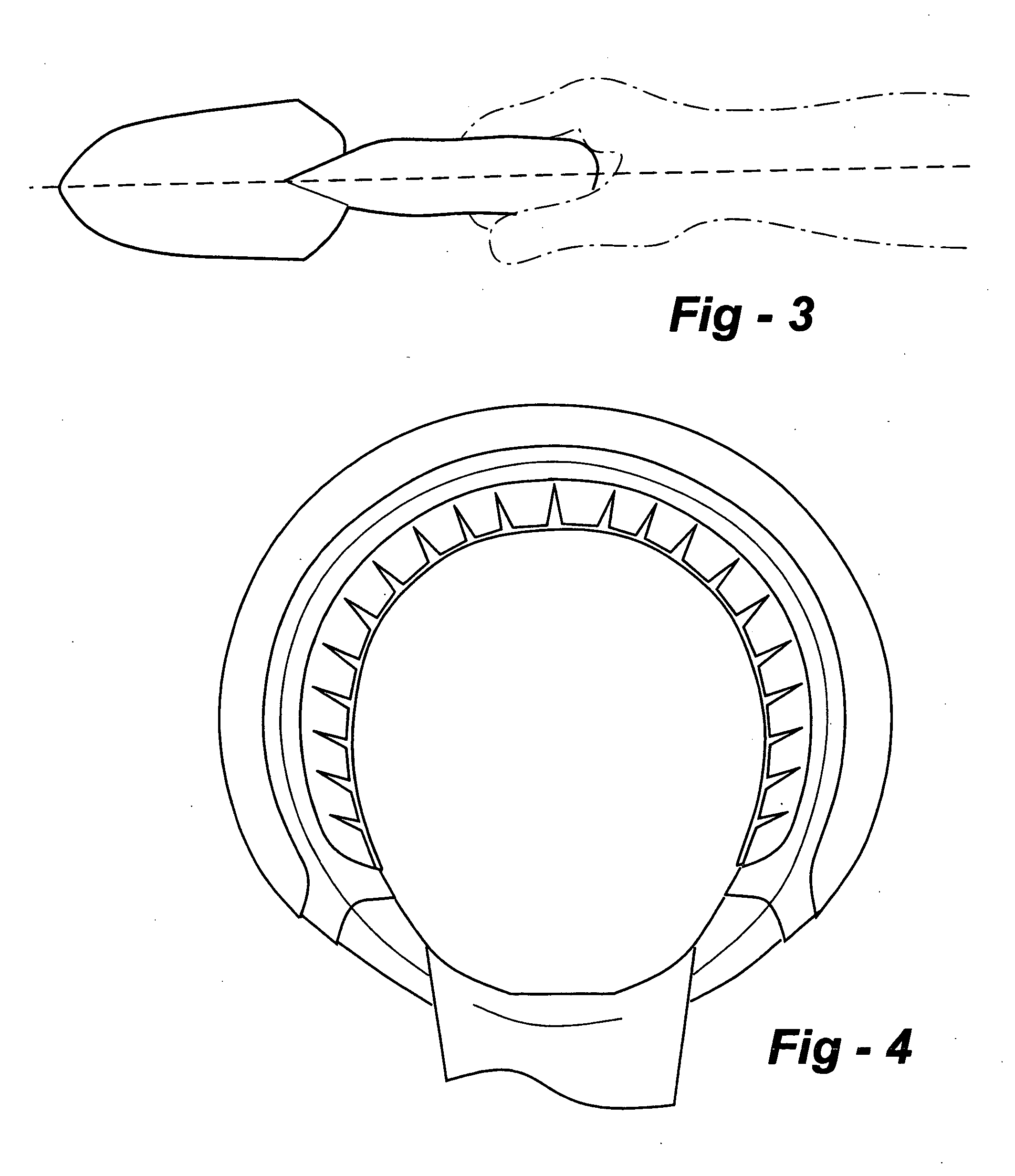
[0011] Grips according to the invention preferably conform in shape, diameter and dimensions to the physical architecture of the hand such that grip tension and compression of the tendons in the wrist and forearm is optimized, minimizing the compressive force on the small muscles, tendons, and ligaments of the fingers, hand, wrist, and forearm, while maximizing the contributive effectiveness of the larger muscles of the forearm, upper arm and shoulder.

Problems solved by technology

Straight handles are not energy efficient, however, because the user must grip the handle to prevent it from sliding in the user's hands.
To prevent blisters and fatigue, the user must increase the grip pressure on the handle, resulting in greater stress on the muscles, tendons, joints and limbs.

Method used


Image

  • Ergonomic hand tools, construction thereof, and packaging therefor
  • Ergonomic hand tools, construction thereof, and packaging therefor
  • Ergonomic hand tools, construction thereof, and packaging therefor

Examples


Embodiment Construction

[0044] As discussed in the Summary of the Invention, this invention facilitates the use of tools, implements or other utensils within their arc of natural use, motion, and / or attack, preferably without requiring extension, flexion, radial deviation, or ulnar deviation of the wrist from the neutral plane of the forearm. In accordance with the invention, with respect to any pushing, pulling, lifting or turning exertion, the wrist and forearm are aligned and centered on the optimal line of attack, such that a line drawn through the center of, and parallel to, the radius and ulna passes through the center of the wrist, through the center of the circumference of the grip, and through the gravitational center of the combined tool, implement (or other utensil) and payload.

[0045] Particularly in the case of any pushing, pulling or lifting motion, the line of attack is oriented through the point of maximum exertive force, such that the effective compressive grip force required to use the to...


PUM

PropertyMeasurementUnit
Strengthaaaaaaaaaa

Abstract

Handles allow hand tools, implements or other utensils to operate within their arc of natural use, motion and attack without requiring extension, flexion, radial deviation, or lunar deviation of the wrist from the neutral plane of the forearm. The preferred embodiments further include a grip shaped to increase the effectiveness of the tool and minimize antagonism between muscles and tendons of the wrist, forearm and upper arm, while maximizing the effectiveness of the gripping force delivered to it by the user. Maintaining the wrist and forearm in a neutral position increases a tool user's potential strength by increasing the synergy between large muscles of the forearm and upper arm and shoulders. Ornamental tool designs, manufacturing techniques, and packaging options are also disclosed.

Description

REFERENCE TO RELATED APPLICATION [0001] This application is a continuation-in-part of U.S. patent application Ser. No. 10 / 821,766, filed Apr. 9, 2004, the entire content of which is incorporated herein by reference.FIELD OF THE INVENTION [0002] This invention relates generally to hand tools and, in particular, to handle designs for garden tools, and the like, which maintain the wrist and / or forearm in a neutral position. BACKGROUND OF THE INVENTION [0003] Most lawn and garden implements, including shovels, rakes, trowels, and so forth, use conventional, straight handles because they are easily manufactured. Straight handles are not energy efficient, however, because the user must grip the handle to prevent it from sliding in the user's hands. To prevent blisters and fatigue, the user must increase the grip pressure on the handle, resulting in greater stress on the muscles, tendons, joints and limbs. Various types of angled handles have been developed in an attempt to overcome these ...

Claims


Application Information

Patent Timeline
IPC IPC(8): B23D1/00E05B1/00B25G1/10B25F1/00B21K1/00
CPCB25G1/102
Inventor BAKER, BRUCE
Owner BAKER BRUCE
Learn More