Systems and methods for mounting roof-mounted photovoltaic arrays including flashing and adhesive pads

Active Publication Date: 2018-06-14
TECSI SOLAR INC
View PDF12 Cites 10 Cited by
  • Summary
  • Abstract
  • Description
  • Claims
  • Application Information

AI Technical Summary

Benefits of technology

[0009]In yet another aspect, a system for flashing a mount of a photovoltaic assembly on a surface includes a flashing with a lower surface and an upper surface. The flashing defines an opening to receive a fastener for secu

Problems solved by technology

Typically, photovoltaic arrays require numerous mounts and, thus, numerous penetrations in the surface.
However, the grommets require pressure to inhibit water intrusion through the openings and may deteriorate over time.
Accordingly, such seals and barriers may not completely and reliably prevent water intrusion into the structure through the penetrations.
However, the rais

Method used


Image

  • Systems and methods for mounting roof-mounted photovoltaic arrays including flashing and adhesive pads
  • Systems and methods for mounting roof-mounted photovoltaic arrays including flashing and adhesive pads
  • Systems and methods for mounting roof-mounted photovoltaic arrays including flashing and adhesive pads

Examples


Example

[0040]Like reference symbols in the various drawings indicate like elements.

DETAILED DESCRIPTION

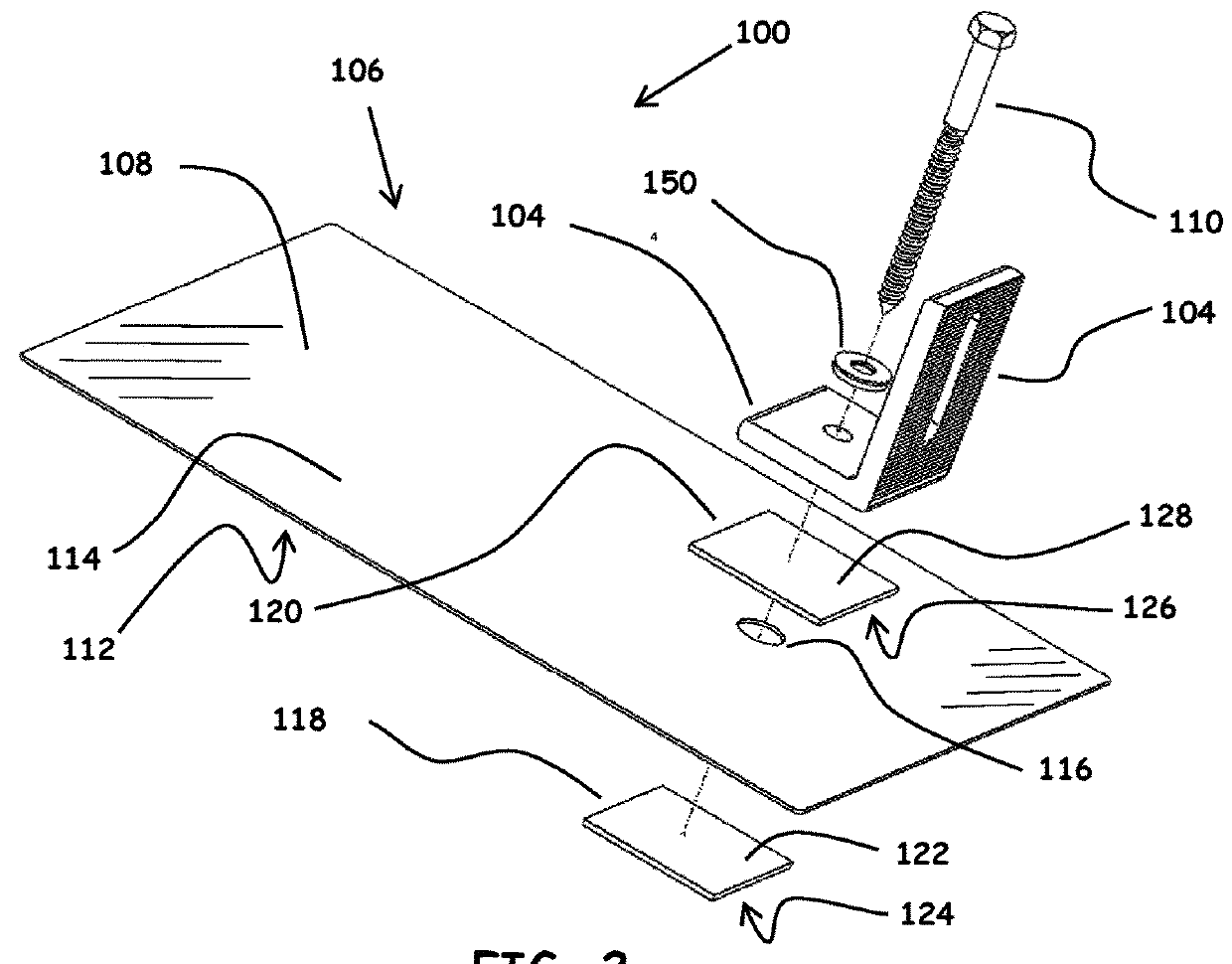
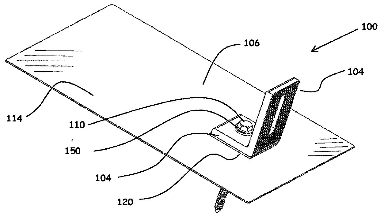
[0041]FIG. 1 is a perspective view of an as installed system 100 for mounting photovoltaic modules and support structures. The system 100 includes a mount 104, a fastener 110, a sealing washer 150, and a flashing assembly 106. FIG. 2 is an exploded perspective view of the system 100 including the flashing assembly 106. FIG. 6 is a sectional view of the as installed system 100 for mounting photovoltaic (PV) modules and photovoltaic support structures on a surface 102 of a structure. The structure may be, for example, a building having a sloped or flat roof or any other structure suitable for mounting PV modules. In the example, the structure is a roof and includes shingles 115 and supports 117.

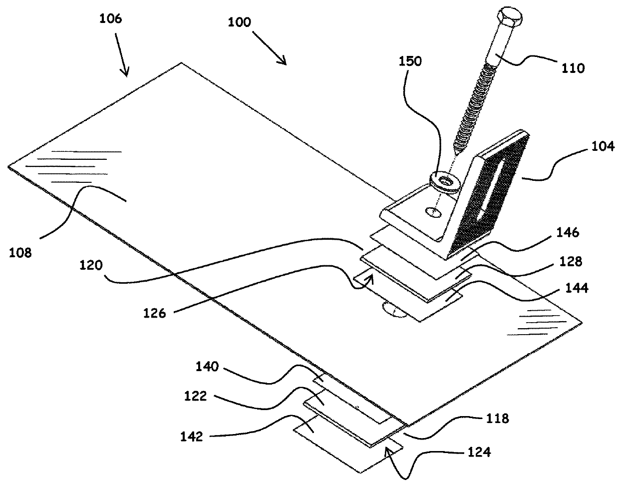
[0042]FIG. 3 is an exploded perspective view of all the components of the system 100 prior to assembly. FIG. 4 shows the top view of the flashing assembly 106. FIG. 5 shows an exploded view of the fl...


PUM


Abstract

A system for flashing a mount of a photovoltaic assembly on a surface includes a flashing including a lower surface and an upper surface. The flashing defines an opening to receive a fastener for securing the mount to the surface. The system also includes a first pad positioned along and attached to the lower surface and a second pad positioned along and attached to the upper surface. The first pad and the second pad extend across the opening. The first pad and the second pad include an adhesive and form a water resistant seal for the opening.

Description

CROSS REFERENCE TO RELATED APPLICATIONS[0001]This application claims priority to U.S. Provisional Application No. 62 / 434,327, filed Dec. 14, 2016, which is hereby incorporated by reference in its entirety.FIELD[0002]This disclosure generally relates to flashing mounting systems for roofs and, more specifically, to flashing mounting systems for roof-mounted photovoltaic arrays.BACKGROUND[0003]Photovoltaic (PV) modules may be mounted to a surface of a structure such as a roof to form PV arrays. Each PV module may be mounted to the surface by mounts that secure the PV module to the surface and elevate the PV module above the surface. Sometimes, securing each mount to the surface causes one or more penetrations in the surface. Typically, photovoltaic arrays require numerous mounts and, thus, numerous penetrations in the surface. However, such penetrations may need to be sealed to prevent water intrusion into the structure through the penetrations. For example, flashing may be positioned...

Claims


Application Information

Patent Timeline
IPC IPC(8): H02S20/23
CPCH02S20/23H02S30/00Y02B10/10Y02E10/50
Inventor TRUTHSEEKER, SAMUEL MARCUS-FLACK
Owner TECSI SOLAR INC
Why Eureka
Try Eureka