Techniques for transmitting or using a pull-in signal to locate a synchronization channel

a technology of synchronization channel and pull-in signal, which is applied in the field of wireless communication systems, can solve the problems blindly searching for a synchronization channel takes time, and achieves the effect of increasing the initial acquisition time (or average initial acquisition time), reducing the search time of the synchronization channel, and increasing the initial acquisition tim

Active Publication Date: 2018-06-14
QUALCOMM INC
View PDF0 Cites 8 Cited by
  • Summary
  • Abstract
  • Description
  • Claims
  • Application Information

AI Technical Summary

Benefits of technology

[0006]Blindly searching for a synchronization channel takes time, is inefficient, and can increase a UE's initial acquisition time (or average initial acquisition time). To decrease a UE's synchronization channel search time, and thereby decrease the UE's initial acquisition time (or average initial acquisition time), a network access device may transmit pull-in signals on one or more raster points of a frequency raster. A pull-in signal may contain information that assists a UE in locating a network access device's synchronization channel transmissions and may indicate, for example, a raster point or timing of a next instance of a synchronization channel transmitted by the network access device. A UE that searches for a synchronization channel on a raster point that does not contain a synchronization channel transmission may identify a pull-in signal on the raster point. The UE may then determine, from the pull-in signal, a second raster point on which a synchronization channel is transmitted, and may search for the synchronization channel on the raster point on which the synchronization channel is transmitted. When the pull-in signal also contains timing information for the synchronization channel, the UE may transition to a power saving state after determining the timing of the synchronization channel, and may transition from the power saving state to an awake state based at least in part on the timing of the synchronization channel.

Problems solved by technology

Blindly searching for a synchronization channel takes time, is inefficient, and can increase a UE's initial acquisition time (or average initial acquisition time).

Method used


Image

  • Techniques for transmitting or using a pull-in signal to locate a synchronization channel
  • Techniques for transmitting or using a pull-in signal to locate a synchronization channel
  • Techniques for transmitting or using a pull-in signal to locate a synchronization channel

Examples


Embodiment Construction

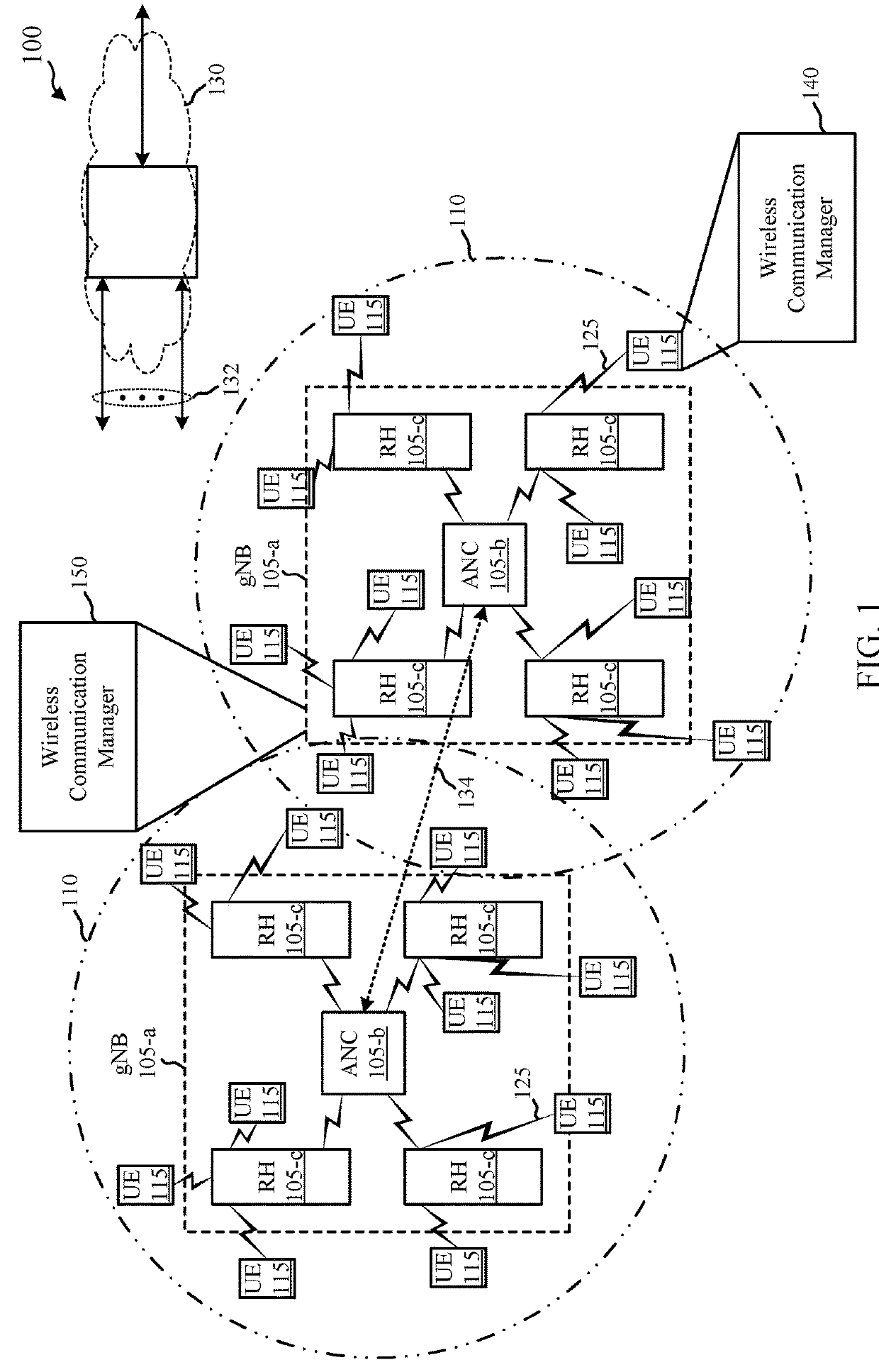
[0047]The present disclosure describes techniques for transmitting or using a pull-in signal to locate a synchronization channel. In a legacy LTE network, a synchronization channel is transmitted every 5 milliseconds (ms). A UE may search for the synchronization channel to collect information needed to access the LTE network. In a LTE unlicensed (LTE-U) network, a synchronization channel may be transmitted every 40 ms. The transmission period of the synchronization channel is longer to be coexistence friendly with Wi-Fi networks. As a result, the initial acquisition time can be longer for a UE that performs an initial access procedure for a LTE-U network (e.g., the UE needs to monitor a raster point longer to test all timing hypotheses for synchronization channel transmission). To potentially decrease a UE's initial acquisition time, a network access device may transmit instances of a synchronization channel within data bursts for which the network access device has already gained a...


PUM


Abstract

Techniques are described for wireless communication. One method includes searching for a synchronization channel on a first raster point of a frequency raster identified for synchronization channel transmission. The frequency raster includes a plurality of raster points in a radio frequency spectrum. The method also includes identifying a pull-in signal on the first raster point; determining, from the pull-in signal, a second raster point of the frequency raster on which the synchronization channel is transmitted; and receiving the synchronization channel on the second raster point. Another method includes transmitting the pull-in signal and the synchronization channel.

Description

CROSS REFERENCES[0001]The present Application for Patent is a Continuation of U.S. patent application Ser. No. 15 / 828,009 by Sun et al., entitled “Techniques for Transmitting or Using a Pull-In Signal to Locate a Synchronization Channel,” filed Nov. 30, 2017, which claims priority to U.S. Provisional Patent Application No. 62 / 429,582 by SUN et al., entitled “Techniques For Transmitting or Using A Pull-In Signal to Locate A Synchronization Channel,” filed Dec. 2, 2016, assigned to the assignee hereof.BACKGROUNDField of the Disclosure[0002]The present disclosure, for example, relates to wireless communication systems, and more particularly to techniques for transmitting or using a pull-in signal to locate a synchronization channel.Description of Related Art[0003]Wireless communication systems are widely deployed to provide various types of communication content such as voice, video, packet data, messaging, broadcast, and so on. These systems may be multiple-access systems capable of s...

Claims


Application Information

Patent Timeline
Patent Type & Authority Applications(United States)
IPC IPC(8): H04J11/00H04J3/06H04J1/06H04J13/00H04W52/02
CPCH04J2211/006H04J2211/005H04W52/0209H04W52/0203H04J11/0073H04J1/06H04J3/0614H04J11/0076H04J13/00H04J11/0086H04L5/005H04L5/0092H04L27/2613H04L27/2692Y02D30/70
Inventor SUN, JINGLUO, TAO
Owner QUALCOMM INC
Why Eureka
Try Eureka