Moving point array solar smelting system

A solar energy and mobile point technology, applied in the field of solar energy utilization, can solve problems such as not suitable for small or household systems, low solar energy collection efficiency, and unusable solar mirrors, etc., to improve utilization time and efficiency, overcome low solar energy collection time, reduce cost effect

Inactive Publication Date: 2013-09-18
CHENGDU AONENGPU TECH
View PDF5 Cites 4 Cited by
  • Summary
  • Abstract
  • Description
  • Claims
  • Application Information

AI Technical Summary

Problems solved by technology

[0007] The tower system is a smelting device that uses a solar mirror as a heliostat and focuses multiple solar mirrors on a smelting device. Due to the characteristics of tower solar energy collection, the utilization time of part of the solar mirror in the tracking solar process is only For example, the solar mirror on the east side of the tower is basically unusable in the morning, and can only be used after noon or afternoon, so the efficiency of solar energy collection is low. This technical solution can achieve high temperature collection, but usually its scale is relatively small. Large, not suitable for small or home systems

Method used


Image

  • Moving point array solar smelting system
  • Moving point array solar smelting system
  • Moving point array solar smelting system

Examples


Embodiment 1

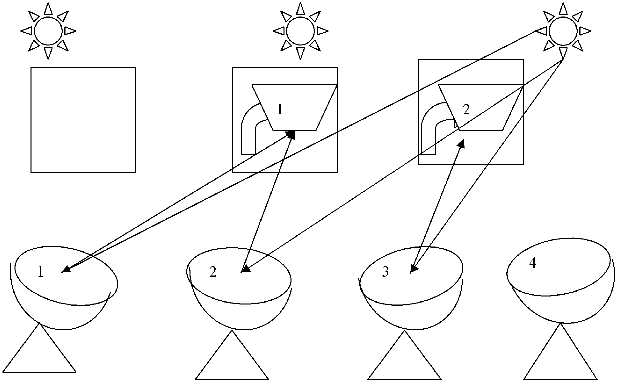
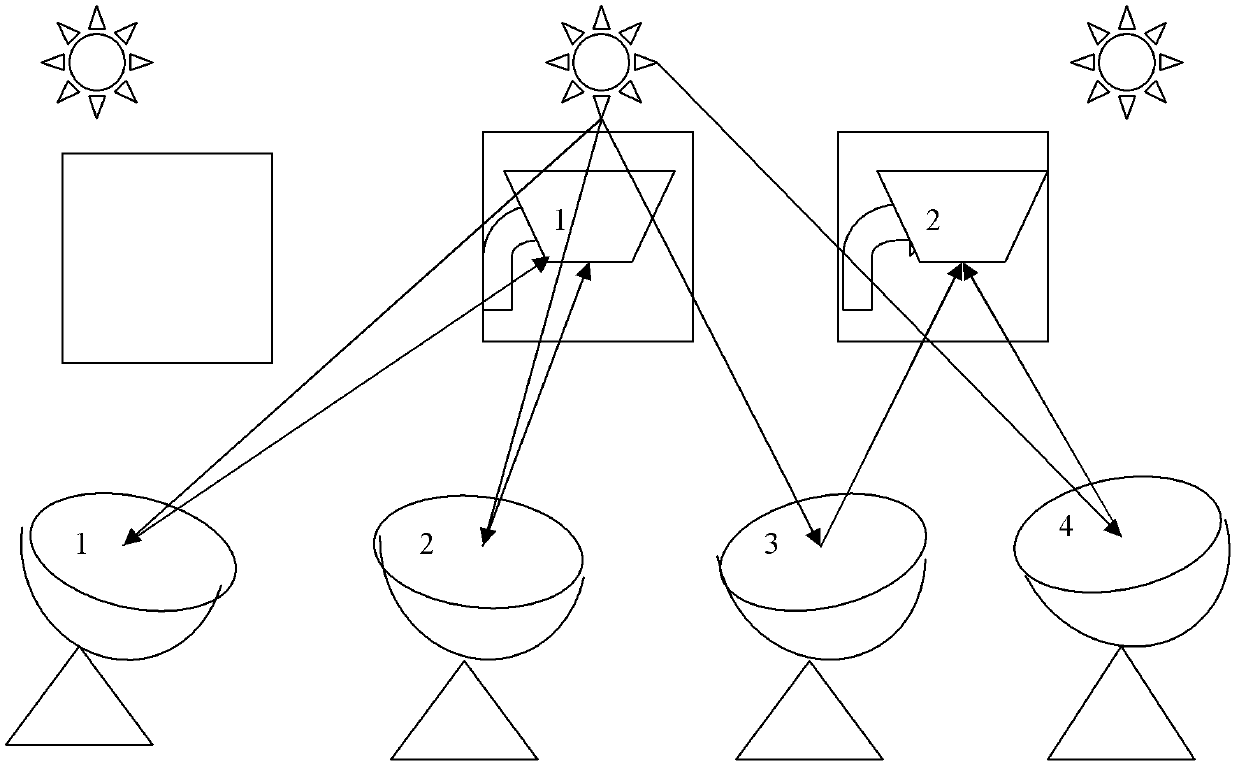
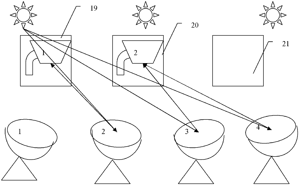
[0072] Embodiment 1: A mobile point array solar energy collection and utilization system composed of 4 solar mirrors and 2 solar energy utilization devices

[0073] as attached figure 1 , 2 , 3 shows the moving point array solar collection and utilization system composed of 4 solar mirrors and 2 smelting devices, figure 1 , 2 , 3 are the collection and utilization of solar energy in the morning, noon and afternoon respectively, figure 1 In the morning, the sun rises from the east, and No. 1, 2 and 3 solar mirrors focus the solar energy on No. 1 and No. 2 smelting devices respectively to realize the tracking and focusing of solar energy; figure 2 At noon, the sun is located in the central area of ​​the sky. No. 1 and No. 2 solar mirrors focus the solar energy on No. 1 smelting device respectively, and No. 3 and No. 4 solar mirrors focus on No. 2 solar storage equipment to realize the tracking and focusing of solar energy; image 3 In the afternoon, the sun falls in the wes...

Embodiment 2

[0074] Embodiment 2: A moving point array solar energy collection and utilization system composed of 12 solar mirrors and 6 solar energy utilization devices

[0075] This example Figure 4 The mobile point array solar collection and utilization system consisting of 12 solar mirrors and 6 smelting devices is shown. The 12 solar mirrors are arranged in an array of three rows and four columns, and the 6 smelting devices are arranged in an array of 3 rows and 2 columns. The smelting devices are respectively arranged in the middle area of ​​the three rows of solar mirrors.

[0076] During different time periods in the morning, noon, and afternoon, solar mirrors 1-12 can choose different smelting devices from 1-6 to focus. According to the actual solar energy collection efficiency, select different focus points to focus, and they are in different positions. The selection of smelting devices that can be focused is also different for solar mirrors 1-12. For solar mirrors 1, 5, 9, 4, 8,...

Embodiment 3

[0079] Embodiment 3: 1*3 moving point solar energy tracking utilization system

[0080] as attached Figure 5 As shown, this embodiment adopts three parabolic dish solar mirrors (2), which are arranged on a parabolic connecting part, and each solar mirror is connected to the parabolic connecting part through a system axis, and the horizontal axis of the system axis The axis and the longitudinal axis are perpendicular to each other. This embodiment is a solar mirror bracket composed of three system axes arranged on the connecting parts. The connecting parts do not move, but the three system axes move. connection, set physical and optical sensors on each solar mirror (2), the solar tracking control device is an integrated electronic control device composed of motor, transmission gear and electronic control part, and adopts a tracking system that complements physical and optical tracking to realize tracking Solar energy tracking. At the same time, the smelting device is equipped...


PUM


Abstract

The invention relates to solar energy utilization, in particular to solar energy collection by using a point focusing solar mirror and application of the point focusing solar mirror to a moving point array solar smelting system. The moving point array solar smelting system at least comprises one or one group of point focusing solar mirrors, at least one smelting device and a tracking control device for control, wherein the solar mirrors are arranged on a solar mirror support; smelting devices are arranged on a smelting device support, and are arranged in a punctiform area focused by the solar mirrors and above or below the solar mirrors; and the tracking control device controls the solar mirrors to focus sunlight to at least one smelting device when the sunlight changes, the smelting devices move in the process that the solar mirrors track solar energy, and each or each group of solar mirrors select the smelting device capable of reaching the highest solar energy utilization efficiency for focusing, so that the solar energy is tracked, focused and utilized.

Description

technical field [0001] The invention relates to the utilization of solar energy, in particular to the use of a point-focused solar mirror to realize solar energy collection, the use of solar point focus to realize the focusing and tracking smelting device of solar energy, and to the focus and utilization of solar energy. Background technique [0002] Solar smelting is the equipment that uses solar energy to realize smelting. [0003] In 1947, French scientist Trumby tried to use the reflector of a military searchlight on a solar melting furnace. In 1952, on the Pyrenees in Mont-Louis, Trumby built the world's first 75-kilowatt solar melting furnace. Large-scale solar smelting furnace, its drying temperature can reach more than 3000 ℃. Trumby hopes to build a larger solar furnace. In the 1970s, a giant solar furnace with a power of 1,000 kilowatts was built. By reflecting bunches of sunlight onto a 50-meter-diameter parabolic concentrator of the solar furnace, the concentra...

Claims


Application Information

Patent Timeline
Patent Type & Authority Applications(China)
IPC IPC(8): F24J2/02F24J2/40F24S20/30
CPCY02E10/47Y02E10/50
Inventor 李建民
Owner CHENGDU AONENGPU TECH
Why Eureka
Try Eureka