Device and System for Placing Securing Device Within Bone

a technology of securing device and bone, which is applied in the direction of image enhancement, ultrasonic/sonic/infrasonic image/data processing, and reradiation, etc., can solve the problems of neurological sequelae, deleterious effects on other systems, pain, sensory overload,

Inactive Publication Date: 2018-06-21
TISSUE DIFFERENTIATION INTELLIGENCE LLC
View PDF0 Cites 33 Cited by
  • Summary
  • Abstract
  • Description
  • Claims
  • Application Information

AI Technical Summary

Benefits of technology

[0006]Present MIS techniques are unable to accurately and consistently detect and avoid key anatomical features, such as neural elements, potentially resulting in profound neurological sequelae and deleterious impacts to other systems. For example, even a minimally invasive surgical instrument, if impacting or contacting with nervous system elements (e.g., nerves, spinal cord) may result in loss of sensation, sensory overload, pain, or other unwanted or harmful effects. Detection and identification of anatomical features may assist in combating these problems and other problems that may become apparent upon reading of this disclosure.

Problems solved by technology

Present MIS techniques are unable to accurately and consistently detect and avoid key anatomical features, such as neural elements, potentially resulting in profound neurological sequelae and deleterious impacts to other systems.
For example, even a minimally invasive surgical instrument, if impacting or contacting with nervous system elements (e.g., nerves, spinal cord) may result in loss of sensation, sensory overload, pain, or other unwanted or harmful effects.

Method used


Image

  • Device and System for Placing Securing Device Within Bone
  • Device and System for Placing Securing Device Within Bone
  • Device and System for Placing Securing Device Within Bone

Examples


Embodiment Construction

[0080]To help understand the present disclosure, the following definitions are provided with reference to terms used in this application.

[0081]Throughout this specification and in the appended claims, when discussing the application of aspects of the present disclosure with respect to the body's tissue, spine or other neural elements, the term “proximal” with respect to such a device is intended to refer to a location that is, or a portion of the device that is, closer to the operator. The term “distal” is intended to refer to a location that is, or a portion of the device, further away from the operator.

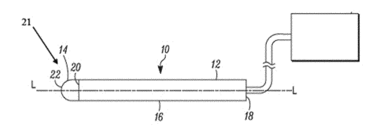
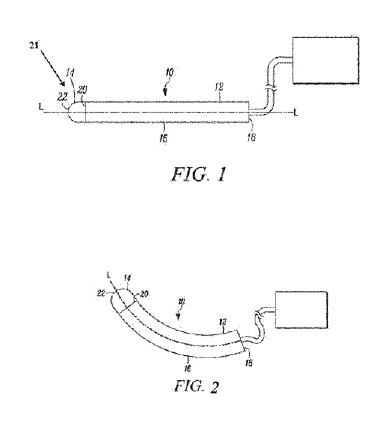
[0082]The embodiments below are described with reference to the drawings in which like elements are referred to by like numerals. The relationship and functioning of the various elements are better understood by the following detailed description. The embodiments as described below are by way of example only and the present disclosure is not limited to the embodiments illustrated in...


PUM


Abstract

Aspects described herein disclose devices, systems, and methods for use in contexts such as minimally invasive surgery (MIS). A device is provided herein having a proximal portion and a distal portion, and an ultrasound transducer may be disposed within the distal portion and configured to scan tissue and identify certain portions of a patent's anatomy. In some aspects, different types of bones may be identified and the information used in determining a drill trajectory. Trajectory information may be presented to an operator of the device visually, such as in a 3-D volumetric image. By scanning the tissue, identifying the anatomy, and presenting the results to an operator, unnecessary damage to elements of the patients anatomy may be avoided or lessened.

Description

CROSS REFERENCE TO RELATED APPLICATIONS[0001]This application claims priority to U.S. Provisional Patent Application Ser. No. 62 / 145,203, filed Apr. 9, 2015 and entitled “Device and Method for Identifying Anatomical Structures”, and to U.S. Provisional Patent Application Ser. No. 62 / 208,759, filed Aug. 23, 2015 and entitled “Device and System for Placing Securing Device within Bone”, and to U.S. Provisional Patent Application Ser. No. 62 / 255,840, filed Nov. 16, 2015 and entitled “Retractor System.” The contents of the applications listed above are hereby incorporated by reference in their entirety for all purposes. This application also incorporates by reference in their entireties for all purposes the following related applications: International Application PCT / US15 / 50404, with an international filing date of Sep. 16, 2015 entitled IDENTIFYING ANATOMICAL STRUCTURES, U.S. Provisional Patent Application Ser. No. 62 / 051,670, filed Sep. 17, 2014 entitled “DEVICE AND METHOD FOR IDENTIF...

Claims


Application Information

Patent Timeline
Patent Type & Authority Applications(United States)
IPC IPC(8): A61B8/08A61B8/12A61B5/00A61B5/04A61B90/00A61B17/16A61B17/00A61B17/17G06N20/10
CPCA61B8/0875A61B8/12A61B5/0066A61B5/0084A61B5/04001A61B90/37A61B17/1671A61B17/00234A61B17/1703A61B8/4488A61B2090/378A61B8/4483A61B5/0035G01S15/8909A61B1/05A61B1/0676A61B1/317A61B17/7032A61B8/0858A61B8/5223G01S7/52036G16H50/20G06N20/10G16H30/40G16H20/40A61B5/24A61B5/389G06V2201/03A61B2090/3782G06T2207/30012A61B2034/107G06T7/11G06V20/698G06F2218/12
Inventor SINGH, KERNGUPTA, SACHIN
Owner TISSUE DIFFERENTIATION INTELLIGENCE LLC
Why Eureka
Try Eureka