
Air supply device and vehicle seat

Inactive Publication Date: 2018-06-21
TOYOTA JIDOSHA KK
View PDF0 Cites 8 Cited by
  • Summary
  • Abstract
  • Description
  • Claims
  • Application Information

AI Technical Summary

Benefits of technology

The patent text discusses how the use of a pump (air supply device) in a vehicle seat can increase in cost and complexity due to the need for a vibration-proof member. The disclosed invention provides an air supply device that reduces vibration and noise, which eliminates the need for the vibration-proof member. This results in a simpler and more cost-effective solution for providing air in vehicle seats.

Problems solved by technology

An increase in the number of components and an increase in manufacturing cost result from the structure in which the pump (air supply device) is disposed with the vibration-proof member interposed.

Method used


Image

  • Air supply device and vehicle seat
  • Air supply device and vehicle seat
  • Air supply device and vehicle seat

Examples


first embodiment

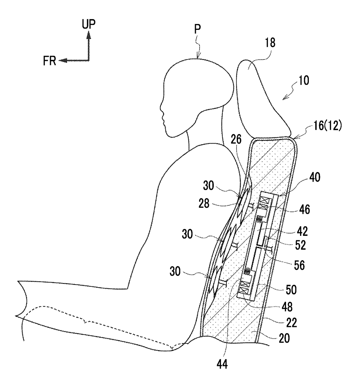
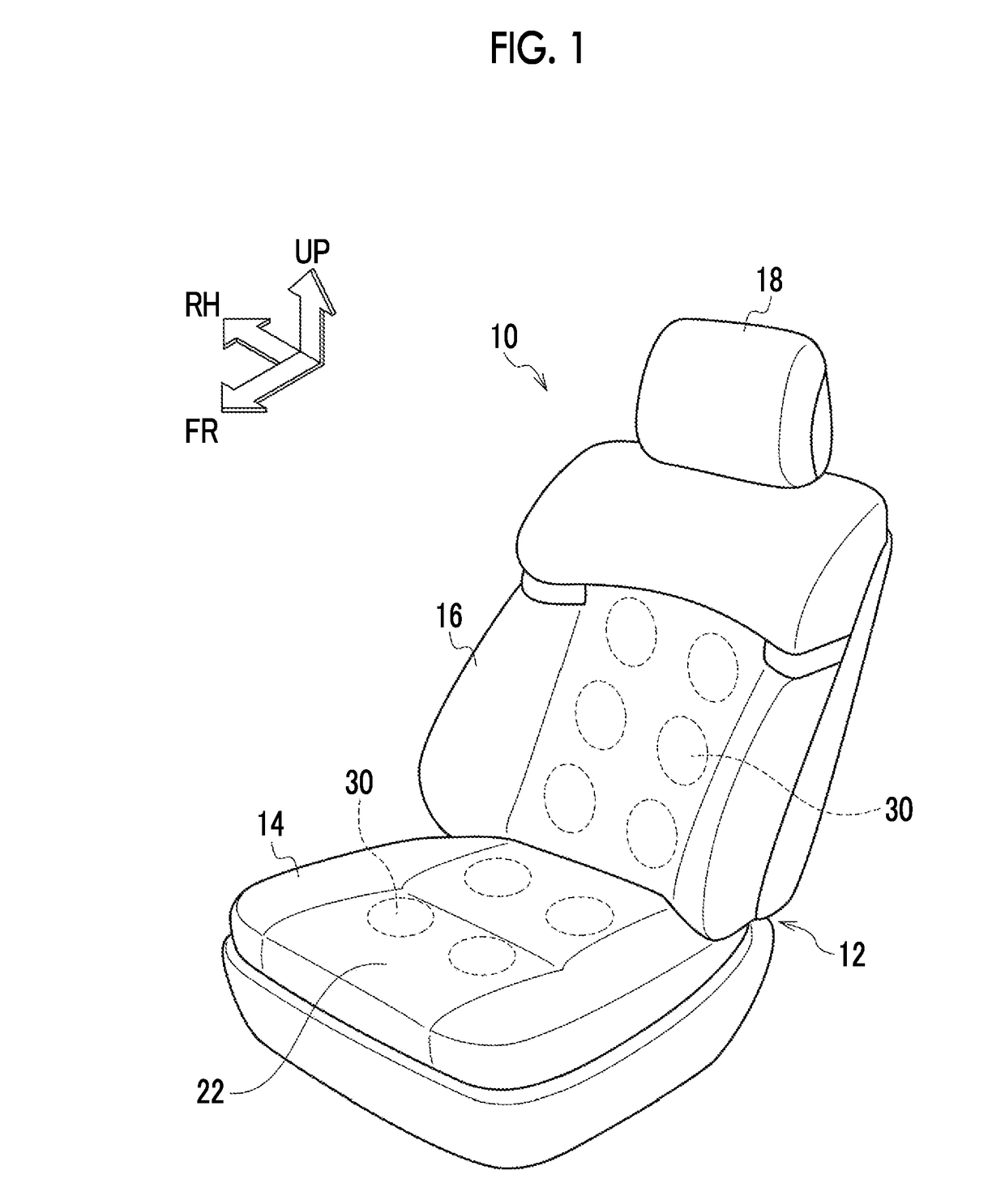
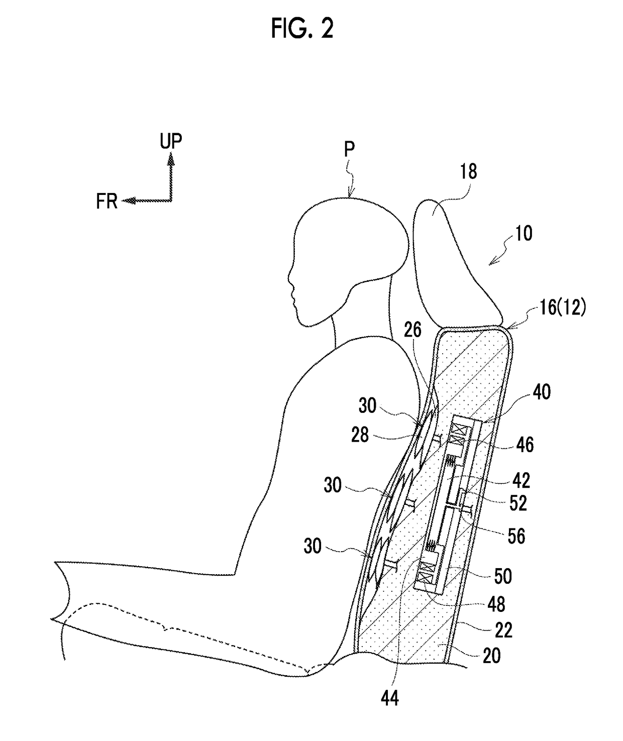
[0032]Hereinafter, an air supply device 40 and an air supply and exhaust device 36 (including an electronic control unit 38) according to a first embodiment, which perform air supply and discharge on each of the airbags 30 and expand and contract the airbags 30 in an individual manner, will be described with reference to FIGS. 2 and 3. The air supply device 40 and the air supply and exhaust device 36 (including the electronic control unit 38) are disposed in the seat back 16 (or in the seat cushion 14).

[0033]As illustrated in FIGS. 2 and 3, the air supply device 40 is provided with a tubular member 42, a pump head 50, and a movable body 44. The tubular member 42 is formed in a bellows shape, is capable of expanding and contracting in its axial direction, and has a substantially rectangular shape in front view. The pump head 50 has a substantially rectangular shape in front view and is attached to a first end portion of the tubular member 42 in the axial direction to block the tubula...

second embodiment

[0060]An air supply device 60 according to a second embodiment will be described below. The same reference numerals will be used to refer to the same parts as in the first embodiment, and detailed description thereof will be appropriately omitted along with the action that is common to the first and second embodiments.

[0061]As illustrated in FIGS. 4 and 5, the air supply device 60 has two shape memory alloy wires (hereinafter, simply referred to as “wires”) 70 as members made of an elongated shape memory alloy that is contracted in an energized state and restored in a non-energized state. The air supply device 60 is configured for a tubular member 42 to be expanded and contracted by the wires 70 causing a movable body 44 to approach and move away from a pump head 50.

[0062]Specifically, pulleys 62, 64, 66, 68, which have the width direction of the seat as their axial direction, are disposed in the vicinity of the upper left corner portion, the lower left corner portion, the lower rig...


PUM


Abstract

Provided is an air supply device including a tubular member, a pump head, and a movable body. The pump head includes an air intake portion through which air flow into the tubular member and an air delivery portion through which the air flown into the tubular member is delivered to an airbag disposed in at least a seat back in a vehicle seat. The movable body is configured such that the tubular member is expanded and contracted, the air is flown into the tubular member from the air intake portion, and the air flown into the tubular member is delivered from the air delivery portion as a result of a reciprocating movement resulting from energization of a coil portion, the movable body approaching and moving away from the pump head during the reciprocating movement.

Description

INCORPORATION BY REFERENCE[0001]The disclosure of Japanese Patent Application No. 2016-248293 filed on Dec. 21, 2016 including the specification, drawings and abstract is incorporated herein by reference in its entirety.BACKGROUND1. Technical Field[0002]The disclosure relates to an air supply device and a vehicle seat provided with an air supply device.2. Description of Related Art[0003]In general, a rolling-type pump is used as an air supply device supplying air to an airbag. The rolling-type pump is a structure in which a piston is moved up and down by becoming eccentric with respect to a motor shaft, and thus the vibration and noise of the rolling-type pump are hardly reduced. Accordingly, in a case where the pump is disposed in a seat back of a vehicle seat, the pump is disposed with a vibration-proof member interposed, which is known in the related art (refer to, for example, Japanese Unexamined Patent Application Publication No. 2009-225843 (JP 2009-225843 A)).SUMMARY[0004]An ...

Claims


Application Information

Patent Timeline
IPC IPC(8): B60N2/90B60N2/02
CPCB60N2002/026B60N2/914B60N2/0244B60N2/665A61H9/0078B60Q9/00B60N2/70B60N2/976F04B45/067B60N2/026F04B43/00
Inventor ONUMA, MASAHIKOKADONO, YUUKI
Owner TOYOTA JIDOSHA KK
Learn More