Brake hydraulic pressure controller and method for manufacturing brake hydraulic pressure controller

a technology manufacturing method, which is applied in the direction of braking system, servomotor components, cycles, etc., can solve the problems of increased man-hours, increased manufacturing cost of brake hydraulic pressure controller, and enlargement of each member, so as to simplify fixation structure and manufacturing process, the effect of suppressing manufacturing cos

Inactive Publication Date: 2018-06-21
ROBERT BOSCH GMBH
View PDF24 Cites 7 Cited by
  • Summary
  • Abstract
  • Description
  • Claims
  • Application Information

AI Technical Summary

Benefits of technology

[0010]The brake hydraulic pressure controller and the method for manufacturing a brake hydraulic pressure controller according to the invention can simp

Problems solved by technology

Such a mechanical fixation structure by means of the screw or the like complicates structures of the coil unit and the base body, and thus produces problems of increased manufacturing cost of the brake hydraulic pressur

Method used


Image

  • Brake hydraulic pressure controller and method for manufacturing brake hydraulic pressure controller
  • Brake hydraulic pressure controller and method for manufacturing brake hydraulic pressure controller
  • Brake hydraulic pressure controller and method for manufacturing brake hydraulic pressure controller

Examples


Embodiment Construction

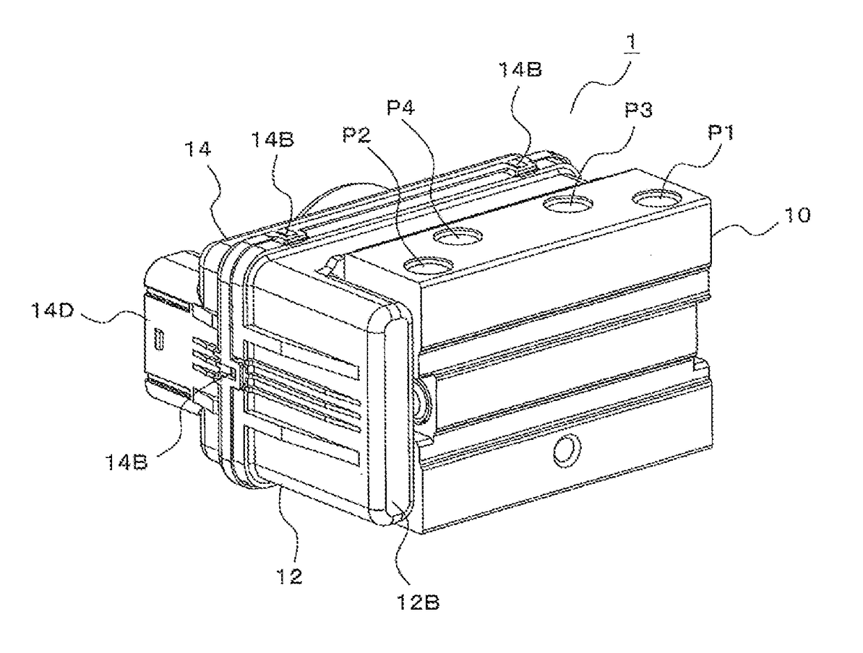
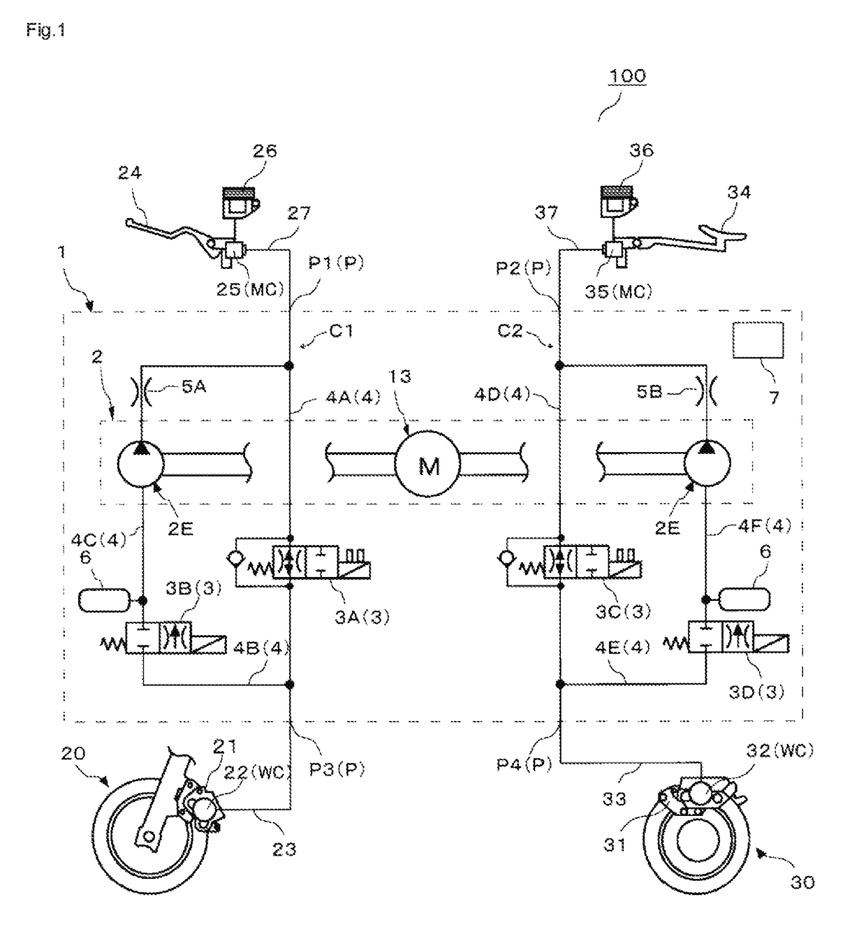
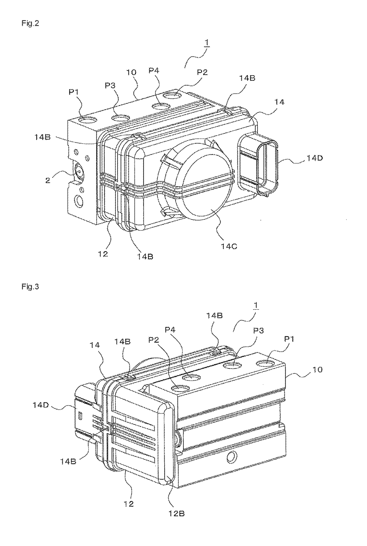
[0028]A description will hereinafter be made on a brake hydraulic pressure controller and a method for manufacturing a brake hydraulic pressure controller according to the invention by using the drawings. Note that the brake hydraulic pressure controller according to the invention may be used in a vehicle other than a motorcycle (for example, an automobile, a track, or the like).

[0029]In addition, each of a configuration, an operation, and the like, which will be described below, is merely one example, and the brake hydraulic pressure controller according to the invention is not limited to a case with such a configuration, such an operation, and the like. For example, the brake hydraulic pressure controller according to the invention may not have a pump device. For example, the brake hydraulic pressure controller according to the invention may perform an operation other than that as an ABS.

[0030]Furthermore, in each of the drawings, detailed portions are appropriately simplified or ...


PUM


Abstract

A purpose is to obtain a brake hydraulic pressure controller and a method for manufacturing a brake hydraulic pressure controller that realize suppression of manufacturing cost and downsizing of the brake hydraulic pressure controller and simplification of a manufacturing process.
The brake hydraulic pressure controller 1 has: a base body 10 formed with a channel of a hydraulic fluid; plural hydraulic pressure regulating valves 3 provided in the channel; and plural drive coils respectively provided in the plural hydraulic pressure regulating valves 3 and driving the hydraulic pressure regulating valves 3. One end section 15B that constitutes one end side of the drive coil 11 is adhered to an adhesive surface section that constitutes a contour of the base body 10 via a first adhesive member 17A.

Description

BACKGROUND OF THE INVENTION[0001]The invention relates to a brake hydraulic pressure controller and a method for manufacturing a brake hydraulic pressure controller.[0002]Conventionally, when a passenger of a vehicle such as a motorcycle (a two-wheeled motorized vehicle or a three-wheeled motorized vehicle) operates a brake lever, pressure of a hydraulic fluid in a brake fluid circuit that is filled with a brake fluid is boosted, and a braking device of the vehicle can thereby generate a braking force on a wheel. In addition, it has been known to adopt an antilock brake system (ABS) as a brake hydraulic pressure controller that adjusts the braking force for a purpose of increasing safety of a braking operation.[0003]This brake hydraulic pressure controller can boost / reduce the pressure of the hydraulic fluid in the brake fluid circuit and adjust the braking force that is generated on the wheel.[0004]As the brake hydraulic pressure controller, an apparatus in which a pump device for ...

Claims


Application Information

Patent Timeline
IPC IPC(8): B60T8/36B60T8/17F15B13/044
CPCB60T8/366B60T8/3645B60T8/3675B60T8/1706F15B13/044F15B2013/004B60T8/368B60Y2200/12
Inventor SAGAYAMA, KOSAKUOGAWA, TAKASHI
Owner ROBERT BOSCH GMBH
Why Eureka
Try Eureka