Fingerprint sensing module and method for manufacturing the fingerprint sensing module

Active Publication Date: 2018-06-21
FINGERPRINT CARDS ANACATUM IP AB
View PDF9 Cites 13 Cited by
  • Summary
  • Abstract
  • Description
  • Claims
  • Application Information

AI Technical Summary

Benefits of technology

[0026]Additionally, the fingerprint sensing module may comprise a mechanical support layer arranged between the fingerprint sensor control device and the second side of said fingerprint sensing module. The mechanical support layer can for example be a compliant polymer based material. A mechanical support layer may increase the flexibility of the sensing module, allowing the module to flex more without breaking. This may be particularly advantageous for a sensing module integrated in a smart card, due to the flexibility of the smart card.
[0027]According to one embodiment of the invention, the fingerprint sensing module may further comprise an electrically conductive bezel arranged adjacent to the sensing array to provide an electrical connection between a finger placed on the sensing surface and drive signal circuitry of the fingerprint sensing module. The bezel may for example be a frame arranged to surround the sensor device such that a finger placed on the sensing surface also makes contact with the bezel. Thereby, a drive signal can be provided to the finger, which facilitates capacitive fingerprint measurement according to established sensing technology. In case of the cover structure being a laminate structure comprising a plurality of conductive layers, the top metal layer in the laminate structure may advantageously be used to form an electrical contact to the bezel. It should however be noted that the sensing module equally well may operate without a bezel, in which case a drive signal

Problems solved by technology

However, the requirements of the fingerprint sensor in a smart card may change compared to when the sensor is used in a smartphone.
However, a gap between the fingerprint sensor module and

Method used


Image

  • Fingerprint sensing module and method for manufacturing the fingerprint sensing module
  • Fingerprint sensing module and method for manufacturing the fingerprint sensing module
  • Fingerprint sensing module and method for manufacturing the fingerprint sensing module

Examples


Example

[0053]In the present detailed description, various embodiments of the module and method according to the present invention are mainly described with reference to a fingerprint sensing module comprising a capacitive fingerprint sensor. Moreover, the fingerprint sensing module is described with reference to integration in a smart card. However, the described module may also be well suited for use in other applications, such a consumer electronic devices, internet-of-things (IoT) and automotive applications.

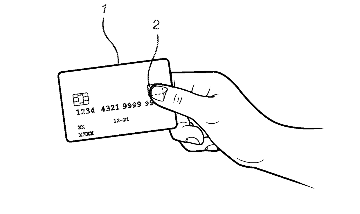
[0054]FIG. 1 schematically illustrates a smart card 1 comprising fingerprint sensing module 2 according to an embodiment of the invention.

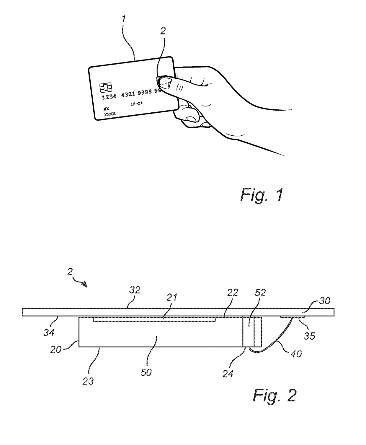
[0055]FIG. 2 schematically illustrates a fingerprint sensing module 2 comprising a fingerprint sensor device 20 having a sensing array 21 arranged on a first side 22 of the device 20. The sensing array 21 comprises an array of fingerprint sensing elements, here electrically conducting plates, configured to detect a capacitive coupling between each...


PUM


Abstract

There is provided a fingerprint sensing module comprising a fingerprint sensor device having a sensing array arranged on a first side of the device. The fingerprint sensor device also comprises connection pads for connecting the fingerprint sensor device to external circuitry and a fingerprint sensor device cover structure, the cover structure having a first side configured to be touched by a finger, and a second side facing the sensing array, wherein the cover structure comprises conductive traces, arranged on the second side, for electrically connecting the fingerprint sensor module to external circuitry, and wherein a surface area of the cover structure is larger than a surface area of the sensor device. Moreover, the fingerprint sensor device comprises wire-bonds electrically connecting the connection pads of the fingerprint sensing device to the conductive traces of the cover structure.

Description

CROSS REFERENCE TO RELATED APPLICATIONS[0001]This application claims priority to Sweden Application No. 1651654-4, filed on Dec. 15, 2016, the disclosure of which is incorporated herein by reference in its entirety.FIELD OF THE INVENTION[0002]The present invention relates to a fingerprint sensing module suitable for integration in smart cards, and to a method for manufacturing such a fingerprint sensing module. The present invention also relates to a smart card comprising such a fingerprint sensing module.BACKGROUND OF THE INVENTION[0003]Various types of biometric systems are used more and more in order to provide increased security and / or enhanced user convenience. In particular, fingerprint sensing systems have been adopted in, for example, consumer electronic devices, thanks to their small form factor, high performance, and user acceptance.[0004]Among the various available fingerprint sensing principles (such as capacitive, optical, thermal etc.), capacitive sensing is most commo...

Claims


Application Information

Patent Timeline
IPC IPC(8): G06K19/14G06K9/00G06K19/18G06K19/077G06V10/94G06V40/13
CPCG06K19/145G06K9/00053G06K9/0002G06K19/18G06K19/0772G06K19/07701G06K19/07354G06V40/13G06V10/94G06V40/1329G06V40/1306H01L2224/73265H01L2924/181H01L2924/19107H01L2924/00012
Inventor LUNDBERG, NILSMO, ZHIMINSLOTTNER, MATS
Owner FINGERPRINT CARDS ANACATUM IP AB
Why Eureka
Try Eureka