

Vibration-wave motor
a vibration-wave motor and motor technology, applied in piezoelectric/electrostriction/magnetostriction machines, mountings, instruments, etc., can solve the problem of difficult to make small ultrasonic motors, and achieve the effect of stably transmitting a driving for
- Summary
- Abstract
- Description
- Claims
- Application Information
AI Technical Summary
Benefits of technology
Problems solved by technology
Method used
Image

Examples
first embodiment
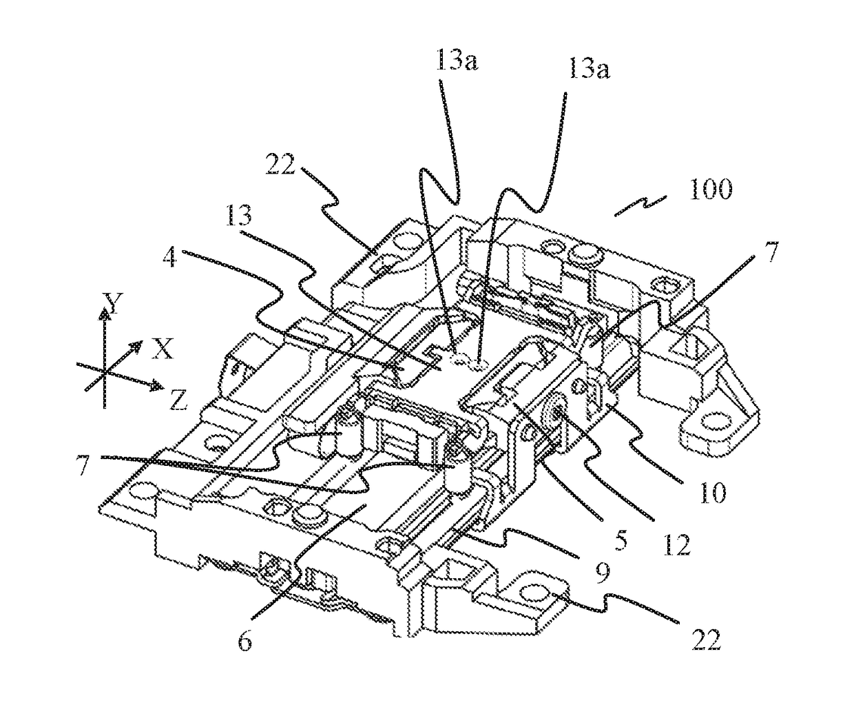
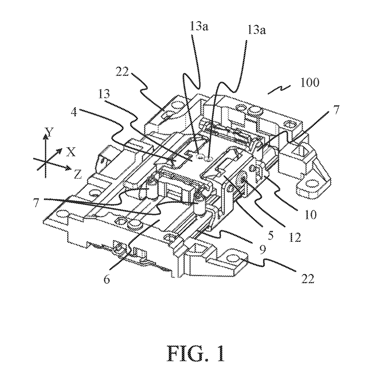
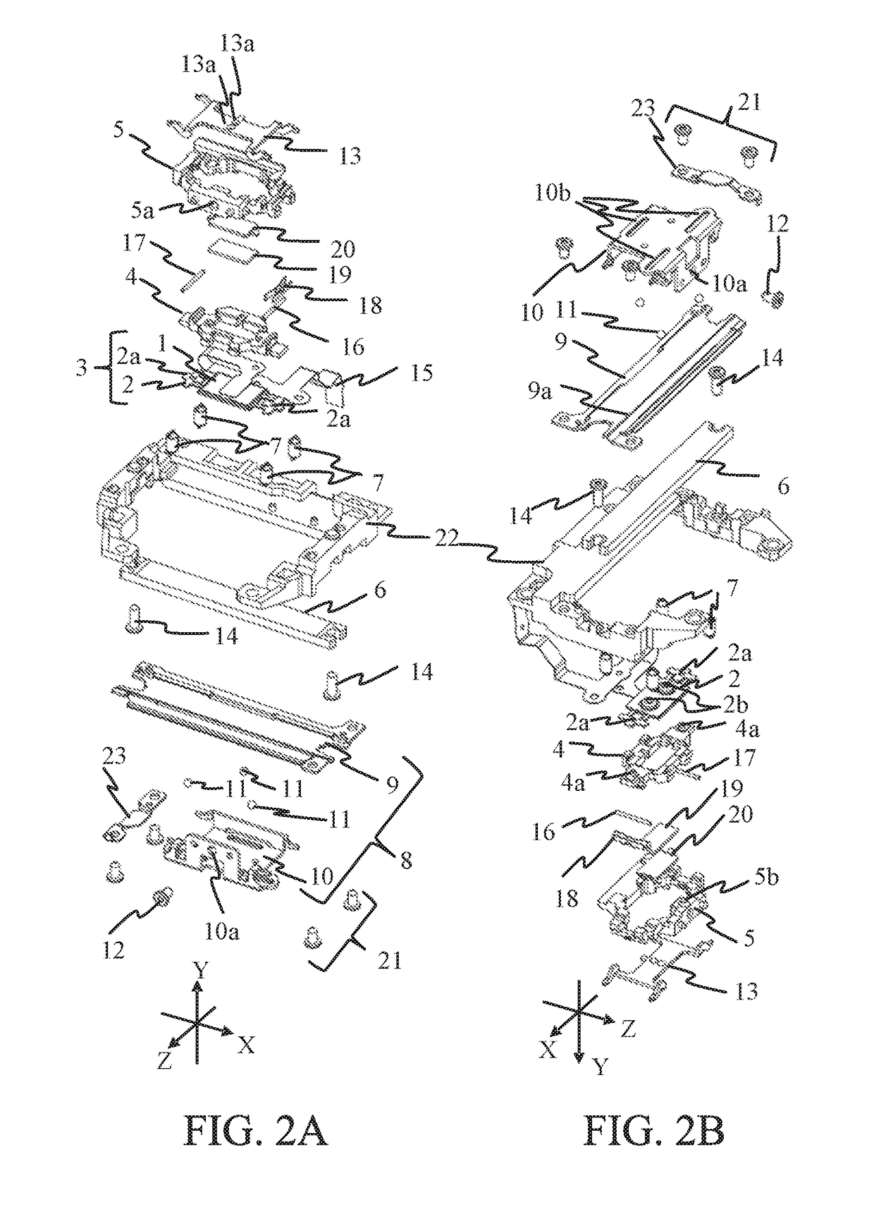
[0024]FIGS. 1 to 3 illustrate a perspective view, exploded perspective views, and a top view of a vibration-wave motor 100 according to this embodiment. FIG. 2A is an exploded perspective view viewed from a top surface side. FIG. 2B is an exploded perspective view viewed from a bottom surface side. FIGS. 4 and 5 are sectional views taken along lines A-A and B-B in FIG. 3, respectively.
[0025]The vibration-wave motor 100 is a linear actuator of a direct-acting type, and can drive an unillustrated driven member in the X-axis direction by generating a driving force in the X-axis direction.
[0026]A description will now be given of a mechanism with which the vibration-wave motor 100 generates the driving force. As illustrated in FIGS. 2A and 2B, the vibration-wave motor 100 includes a vibrator 3 that includes a piezoelectric element 1 and a vibration plate (elastic plate) 2 adhered to each other by the adhesive agent, etc. A flexible substrate 15 is mechanically and electrically connected ...
second embodiment
[0043]FIG. 6 is a sectional view of a principal part of an image pickup apparatus (optical apparatus) 200 that includes a vibration-wave motor 100 according to the first embodiment. The image pickup apparatus 200 includes a camera body 101 that includes an image pickup element 101a, and a lens barrel 102 detachably attached to the camera boy 101 via a mount 111. The lens barrel 102 has an approximately rotationally symmetrical shape, and FIG. 6 illustrates only its upper half. A description of the same configuration as that in the first embodiment will be omitted.
[0044]The lens barrel 102 includes an outer cylinder 112 fixed onto the mount 111 by an (unillustrated) screw. The outer cylinder 112 includes a front barrel 113 configured to hold a lens G1 and a back barrel (fixing cylinder) 204 configured to hold and a lens G3. The back barrel 204 is fixed onto an unillustrated flange part of a base member 22 of the vibration-wave motor 100 by a screw etc. A guide bar 202 is held by the ...
third embodiment
[0055]This embodiment discusses a lens driving apparatus 400 in which a driven member is driven by a vibration-wave motor 300 having a structure different from that of the vibration-wave motor 100 according to the first embodiment. The vibration-wave motor 300 has the same basic configuration as that of the vibration-wave motor 100 but has a different configuration of the fixing part for coupling the base holding frame and the move plate with each other. A description of the same configuration as that of the vibration-wave motor 100 will be omitted.
[0056]FIG. 12 is a perspective view of a lens driving apparatus 400. FIG. 13 is a top view of a principal part of the lens driving apparatus 400. FIGS. 14 and 15 are sectional views taken along lines J-J and K-K in FIG. 13, respectively.
[0057]In the vibration-wave motor 300, a base holding frame (second holding member) 35 does not have a driving force transmitting part, but a move plate (movable member) 40 includes a driving force transmi...
PUM
 Abstract
Description
Claims
Application Information