
Binding post component for aviation power distribution product

A terminal and product technology, applied in the assembly/disassembly of contacts, multi-conductor connectors, etc., can solve the problems of difficult installation of metal pin terminals, low practicability, and falling off terminals, so as to improve adaptability and Practicality, improved stability and security, effects of close connection

Active Publication Date: 2020-05-19
温州派瑞机械科技有限公司
View PDF10 Cites 2 Cited by
  • Summary
  • Abstract
  • Description
  • Claims
  • Application Information

AI Technical Summary

Problems solved by technology

[0006] In order to solve the above-mentioned technical problems, the present invention provides a terminal component for aviation power distribution products, to solve the problem that there are generally irregularly distributed metal pins and metal pinholes inside the male and female plug connectors of the existing terminal. When docking, it is necessary to align the metal pinholes with the metal pins to complete the connection. In the case of insufficient light, the arrangement of the metal pins cannot be seen clearly, which makes the installation of the terminal posts very difficult and poor adaptability. Frequent vibrations are generally generated during use. Whether the traditional terminal is screwed or plugged in, the terminal may fall off due to the vibration accompanying the power distribution product during use, resulting in the interruption of power transmission of the terminal and the failure of the power supply. If the phenomenon occurs, if this kind of terminal is used on aerospace equipment, it will cause a large safety hazard and the problem of low practicability

Method used


Image

  • Binding post component for aviation power distribution product
  • Binding post component for aviation power distribution product
  • Binding post component for aviation power distribution product

Examples


Embodiment

[0035] as attached figure 1 to attach Figure 8 Shown:

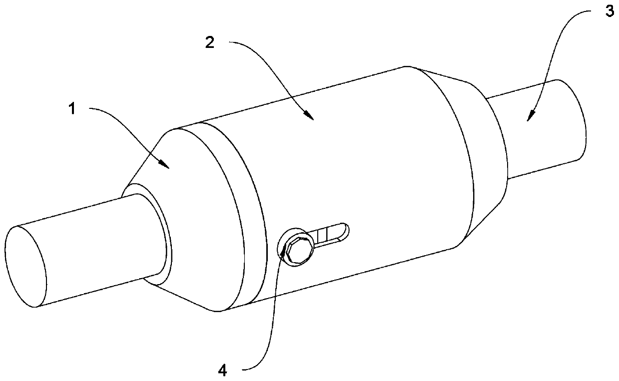
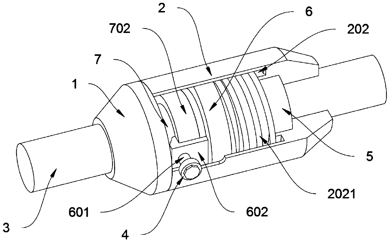
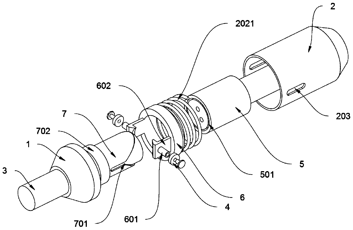
[0036] The invention provides a terminal component for aviation power distribution products, including a fixed block 1, a protective cover 2 and a push block 4; the side of the fixed block 1 is fixedly connected with a pin 7; The outside of the cable 3; the inner end of the protective cover 2 is provided with a turning groove 201, the outer diameter of the turning groove 201 is the same as the outer diameter of the post 5, and the inner diameter of the turning groove 201 is the same as the outer diameter of the cable 3, as attached figure 2 And attached Figure 4 As shown, this design makes when pushing the protective cover 2 to drive the inserting post 5 to move to the inside of the pin post 7, the inserting post 5 can rotate by itself under the action of the positioning block 5011 to complete the insertion of the inserting post 5 and the pin post 7, and the protective cover 2 will not rotate, making the installatio...


PUM


Abstract

The invention discloses a binding post component for an aviation power distribution product, relates to the technical field of binding posts, and solves the problems that the binding post is very difficult to install due to the fact that the arrangement condition of metal pins cannot be seen clearly when the binding post is in butt joint under the condition of insufficient light, and the binding post may fall off due to vibration accompanied by a power distribution product in the use process. The binding post component for the aviation power distribution product comprises a fixing block, a protective cover and a push block. The cable is electrically connected with metal pin holes and metal pins in inserting columns and pin columns. The device can automatically align the metal pins to the metal pin holes instead of manually aligning the metal pins to the metal pin holes, and can be suitable for installation in the environment with insufficient light; a locking block of an anti-falling ring is clamped to one end of a baffle ring, so that the connection relation between the inserting columns and the pin columns can be tighter, and the phenomenon that the inserting columns are separated from the pin columns under frequent and violent vibration can be avoided.

Description

technical field [0001] The invention belongs to the technical field of terminal structure, and more specifically relates to a terminal component for aviation power distribution products. Background technique [0002] The terminal part is a common power input and insulation protection component on high-power power distribution equipment. It is widely used in civil and military power system power distribution equipment to realize high-power power transmission and insulation protection functions. The terminal part is mainly divided into two parts: the terminal post and the insulating part. The terminal post completes the power transmission, and is generally made of copper or stainless steel. The insulating part plays the role of fixing and insulating protection, and the composite material with good mechanical strength and insulation is selected. [0003] For example, in the patent with the application number: CN201710185263.8, a switch cabinet is disclosed. The key points of it...

Claims


Application Information

Patent Timeline
IPC IPC(8): H01R11/03
CPCH01R43/20
Inventor 竺锦苗
Owner 温州派瑞机械科技有限公司
Learn More