Communication system

Active Publication Date: 2018-06-21
MITSUBISHI ELECTRIC CORP
View PDF2 Cites 13 Cited by
  • Summary
  • Abstract
  • Description
  • Claims
  • Application Information

AI Technical Summary

Benefits of technology

The communication system described in this patent allows a device to switch between different types of cells without interrupting the connection. This improves the reliability and quality of the communication.

Problems solved by technology

The RACH involves a collision risk.
Widespread use of smartphones and tablet terminals explosively increases traffic in cellular radio communications, causing a fear of insufficient radio resources all over the world.

Method used


Image

  • Communication system
  • Communication system
  • Communication system

Examples


first embodiment

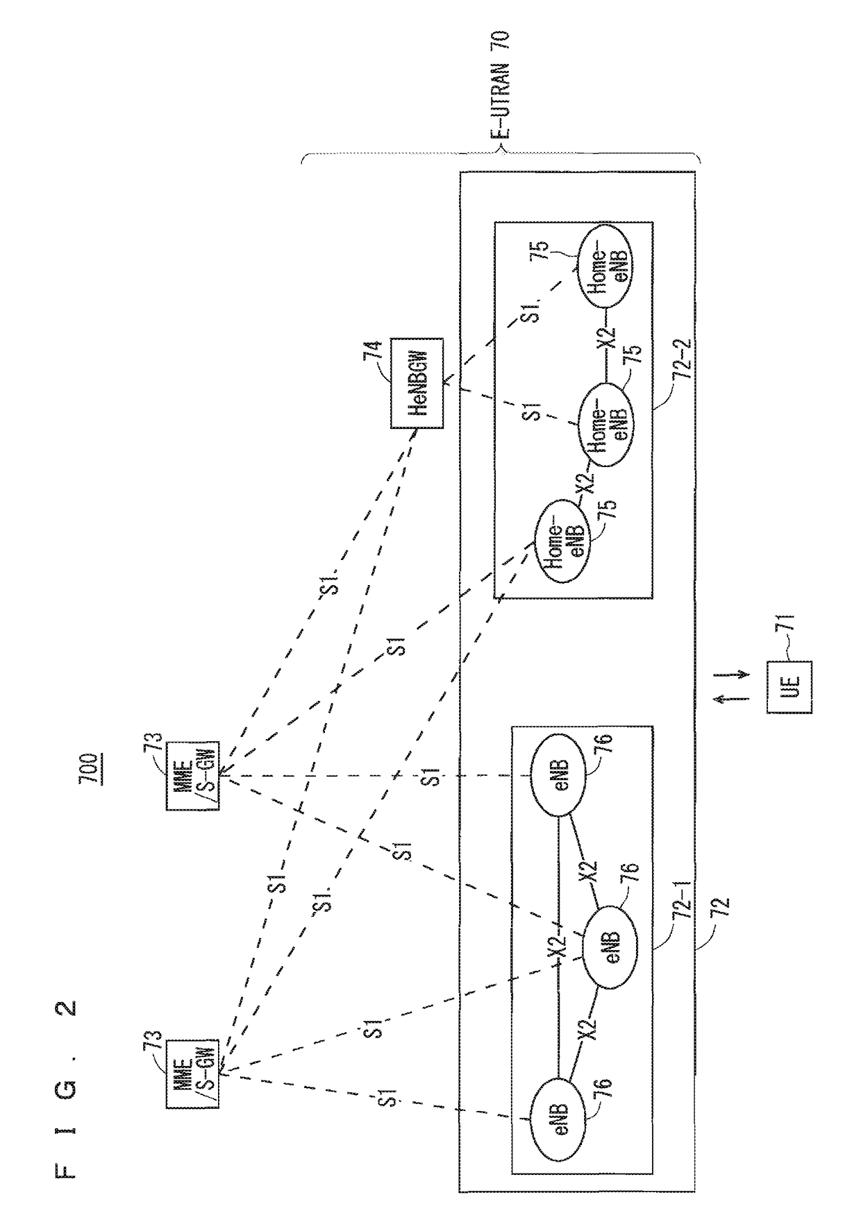
[0103]FIG. 2 is a block diagram showing an overall configuration of an LTE communication system 700, which is under discussion of 3GPP. FIG. 2 will be described. A radio access network is referred to as an evolved universal terrestrial radio access network (E-UTRAN) 70. A user equipment device (hereinafter, referred to as a “user equipment (UE)”) 71 that is a communication terminal device is capable of radio communication with a base station device (hereinafter, referred to as a “base station (E-UTRAN Node B: eNB)”) 72 and transmits and receives signals through radio communication.

[0104]The E-UTRAN is composed of one or a plurality of base stations 72, provided that a control protocol for a user equipment 71 such as a radio resource control (RRC), and user planes such as a packet data convergence protocol (PDCP), radio link control (RLC), medium access control (MAC), or physical layer (PHY) are terminated in the base station 72.

[0105]The control protocol radio resource control (RRC)...

first modification

of First Embodiment

[0219]FIG. 14 shows an example sequence of a handover-related process in a communication system of a first modification of the first embodiment of the present invention. FIG. 15 shows an example sequence of a pre-HO process in step ST1009 of FIG. 14. FIG. 16 shows an example sequence of a post-HO process in step ST1010 of FIG. 14. The handover-related process of this modification is similar to the handover-related process of the first embodiment shown in FIGS. 10 to 13 described above, and thus, the same steps will be denoted by the same step numbers, and description thereof will be omitted.

[0220]This embodiment will disclose a method in which a UE during dual connectivity performs HO between macro cells in the case of Alternative 3C of the user plane architecture of dual connectivity described in Non-Patent Document 11 (see 8.1.1.8 of Non-Patent Document 11).

[0221]In Alternative 3C of the user plane architecture, by the MeNR, between the MeNB and the UE, bearer s...

second embodiment

[0232]FIGS. 17 to 19 show an example sequence of a handover-related process in a communication system of a second embodiment of the present invention. FIG. 17 is continuous with FIG. 18 at a boundary BL1. FIG. 18 is continuous with FIG. 19 at a boundary BL2. The handover-related process of this embodiment is similar to the handover-related process of the first embodiment shown in FIGS. 10 to 13 described above, and thus, the same steps will be denoted by the same step numbers and common description will be omitted.

[0233]This embodiment will disclose a method of performing HO without releasing a SeNB in the case of Alternative 1A of the user plane architecture of dual connectivity described in Non-Patent Document 11 (see 8.1.1.1 of Non-Patent Document 11).

[0234]In Alternative 1A of the user plane architecture, in steps ST902 and ST903, communication is performed through two paths: a path through which communication is performed from the S-GW via the MeNB using the bearer 1 in steps S...


PUM


Abstract

When being connected to a macro cell (S-MeNB) and a small cell (SeNB), a user equipment device performs a pre-handover process of disconnecting the connection with the SeNB before a handover process of switching a macro cell connected with the UE from the macro cell (S-MeNB) that is a moving source to a macro cell (T-MeNB) that is a moving destination along with moving of the UE, and after the handover process, performs a post-handover process of reestablishing the connection with the SeNB.

Description

TECHNICAL FIELD[0001]The present invention relates to a communication system in which radio communication is performed between a communication terminal device and a base station device.BACKGROUND ART[0002]The 3rd generation partnership project (3GPP), the standard organization regarding the mobile communication system, is studying new communication systems referred to as long term evolution (LTE) regarding radio sections and system architecture evolution (SAE) regarding the overall system configuration including a core network and a radio access network, which will be hereinafter collectively referred to as a network as well (for example, see Non-Patent Documents 1 to 10). This communication system is also referred to as 3.9 generation (3.9 G) system.[0003]As the access scheme of the LTE, orthogonal frequency division multiplexing (OFDM) is used in a downlink direction and single carrier frequency division multiple access (SC-FDMA) is used in an uplink direction. Further, differentl...

Claims


Application Information

Patent Timeline
IPC IPC(8): H04W36/08H04W36/28H04W16/32H04L5/00
CPCH04W36/08H04W36/28H04W16/32H04L5/0053Y02D30/70H04W36/00695H04W36/087H04W36/0069
Inventor OHARA, TAKUYASUEMITSU, TAISEIMOCHIZUKI, MITSURUSUZUKI, KUNIYUKINAKAZAWA, MASAYUKIHIRAMATSU, DAISUKE
Owner MITSUBISHI ELECTRIC CORP
Why Eureka
Try Eureka