Method and system for adjusting the refractive power of an implanted intraocular lens

a technology of intraocular lens and refractive power, which is applied in the field of intraocular lens devices, can solve the problems of post-surgical refractive errors and less than satisfactory

Inactive Publication Date: 2018-06-28
LENSGEN INC
View PDF0 Cites 25 Cited by
  • Summary
  • Abstract
  • Description
  • Claims
  • Application Information

AI Technical Summary

Benefits of technology

[0008]In a second aspect of this embodiment, the surface of the intraocular lens may be ablated to thin the intraocular lens to provide a greater amplitude of accommodation of the intraocular lens.
[0009]In a third aspect of this embodiment, the laser may be used to ablate a pattern onto the surface of the intraocular lens. In a further aspect, the pattern may comprise a circular region of the surface of the intraocular lens. Alternatively, the pattern may comprise a ring-shaped region of the surface of the intraocular lens. In yet another aspect, the pattern may comprise arcuate ablations. The arcuate ablations may correct an astigmatism on the patient's eye.
[0012]In another embodiment, a method for adjusting the refractive power of a fluid-filled intraocular lens implanted into a patient's eye is described. The method comprises ablating a portion on either one or both of an anterior region and / or a posterior region of the implanted fluid-filled intraocular lens. The ablating maintains the integrity of the fluid-filled intraocular lens.

Problems solved by technology

However, various confounding factors such as errors in geometrical measurement of the eye, post-surgical changes in the lens position and unexpected anatomical features of an eye may induce post-surgical refractive errors.
For various reasons, a vast majority of these lenses achieve only a limited range (amplitude) of accommodation, which is less than satisfactory.

Method used


Image

  • Method and system for adjusting the refractive power of an implanted intraocular lens
  • Method and system for adjusting the refractive power of an implanted intraocular lens
  • Method and system for adjusting the refractive power of an implanted intraocular lens

Examples


Embodiment Construction

[0033]Specific, non-limiting embodiments of the present invention will now be described with reference to the drawings. It should be understood that such embodiments are by way of example only and merely illustrative of but a small number of embodiments within the scope of the present invention. Various changes and modifications obvious to one skilled in the art to which the present invention pertains are deemed to be within the spirit, scope and contemplation of the present invention as further defined in the appended claims.

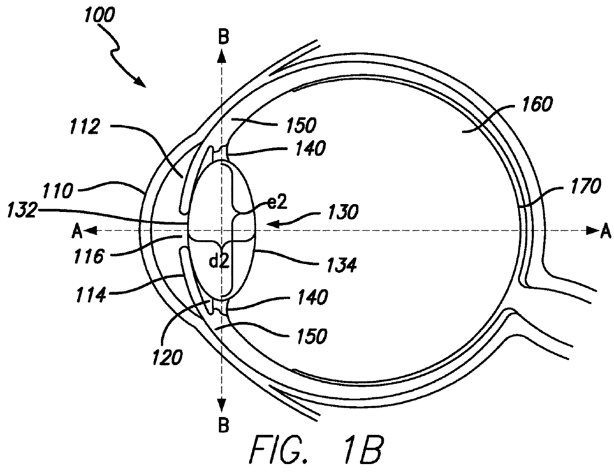
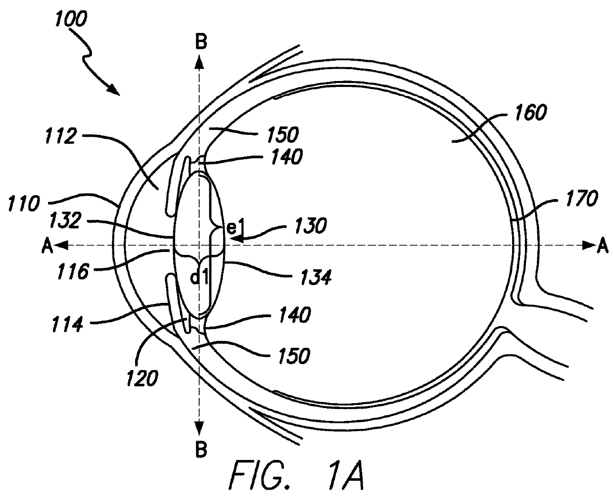
[0034]As shown in FIGS. 1A-B, the human eye 100 comprises three chambers of fluid: the anterior chamber 112, the posterior chamber 120 and the vitreous chamber 160. The anterior chamber 112 corresponds generally to the space between the cornea 110 and the iris 114 and the posterior chamber 120 corresponds generally to the space bounded by the iris 114, the lens 130 and zonule fibers 140 connected to the periphery of the lens 130. The anterior chamber 112 and th...


PUM


Abstract

A method for adjusting the refractive power of a fluid-filled intraocular lens implanted into a patient's eye. The method comprises selecting a pattern to cause a flattening of the intraocular lens or an increase in curvature of the intraocular lens, and ablating the pattern, onto either an optical element of the intraocular lens or a flexible element of the intraocular lens, to alter either one or both of a refractive power and an amplitude of accommodation of the intraocular lens. The ablating occurs while the intraocular lens remains implanted in the patient's eye. The ablating maintains the integrity of a fluid-filled interior cavity defined between the optical element and the flexible element, but causes the flattening of the intraocular lens or the increase in curvature of the intraocular lens.

Description

CROSS-REFERENCE TO RELATED APPLICATION[0001]The present application claims priority to U.S. patent application Ser. No. 14 / 397,567, filed Oct. 28, 2014, which is a national stage application pursuant to 35 U.S.C. § 371 of International Application No. PCT / US2013 / 038943, filed Apr. 30, 2013, which claims priority to U.S. Provisional Application No. 61 / 640,518, filed Apr. 30, 2012, the entire contents of which are incorporated into this application by reference.FIELD OF THE INVENTION[0002]The present invention relates generally to intraocular lens devices and, more particularly, to systems and methods for post-operatively changing and / or adjusting the refractive power of an intraocular lens by a laser.BACKGROUND[0003]Cataract surgery and intraocular lens (IOL) implantation are one of the most commonly performed surgeries in the world. The objective of the surgery is that the implanted IOL will achieve complete correction of cumulative refractive error of the eye undergoing surgery. Ho...

Claims


Application Information

Patent Timeline
Patent Type & Authority Applications(United States)
IPC IPC(8): A61F9/008A61F2/16
CPCA61F9/00838A61F9/00834A61F9/00812A61F2/16A61F2009/0087A61F2250/0003A61F2/1624A61F2009/00887A61F2009/00885
Inventor RAO, RAMGOPALSILVESTRINI, THOMAS
Owner LENSGEN INC
Why Eureka
Try Eureka