Container for discharging powder

a technology for discharging containers and powders, which is applied in the direction of single-unit apparatuses, packaged goods, and packaging foodstuffs, etc., can solve the problems of power leakage through the discharging hole, user inconvenience, and so as to prevent the risk of losing the opening/closing member

Active Publication Date: 2018-06-28
YONWOO CO LTD
View PDF8 Cites 3 Cited by
  • Summary
  • Abstract
  • Description
  • Claims
  • Application Information

AI Technical Summary

Benefits of technology

[0024]As described as the above, a container for discharging powder is configured in a way that a discharging hole of a button part and a connecting hole of a stem are connected or dislocated according to rotation directions, and an opening / closing member inserted into the stem inside the button part ascends / descends according to a rotation of the button part and thereby opens / closes a movement hole of the stem, such that it will solve inconvenience problems such as attaching / detaching the opening / closing member whenever using as well as preventing a risk of losing the opening / closing member, thereby providing user convenience.

Problems solved by technology

However, a user should hold the puff (60) with one hand and then pressurize an operational plate (50) while holding the container body (10) with the other hand, thereby resulting in user inconvenience.
However, since an opening / closing member which opens / closes the discharging hole is configured to have to be attached / detached to the button part, there arises not only a risk of losing the opening / closing member but also a problem that the power may be leaked through the discharging hole in case the container is shaken or dropped in a state of the discharging hole not being closed by the opening / closing member.
Furthermore, there is another problem that the opening / closing member should be detached from the button part before using and be coupled to the button part after using, thus leading to user inconvenience.

Method used


Image

  • Container for discharging powder
  • Container for discharging powder
  • Container for discharging powder

Examples


Embodiment Construction

[0031]Hereinafter, exemplary embodiments will be described in detail with reference to the accompanying drawings. The same reference numerals provided in the drawings indicate the same members.

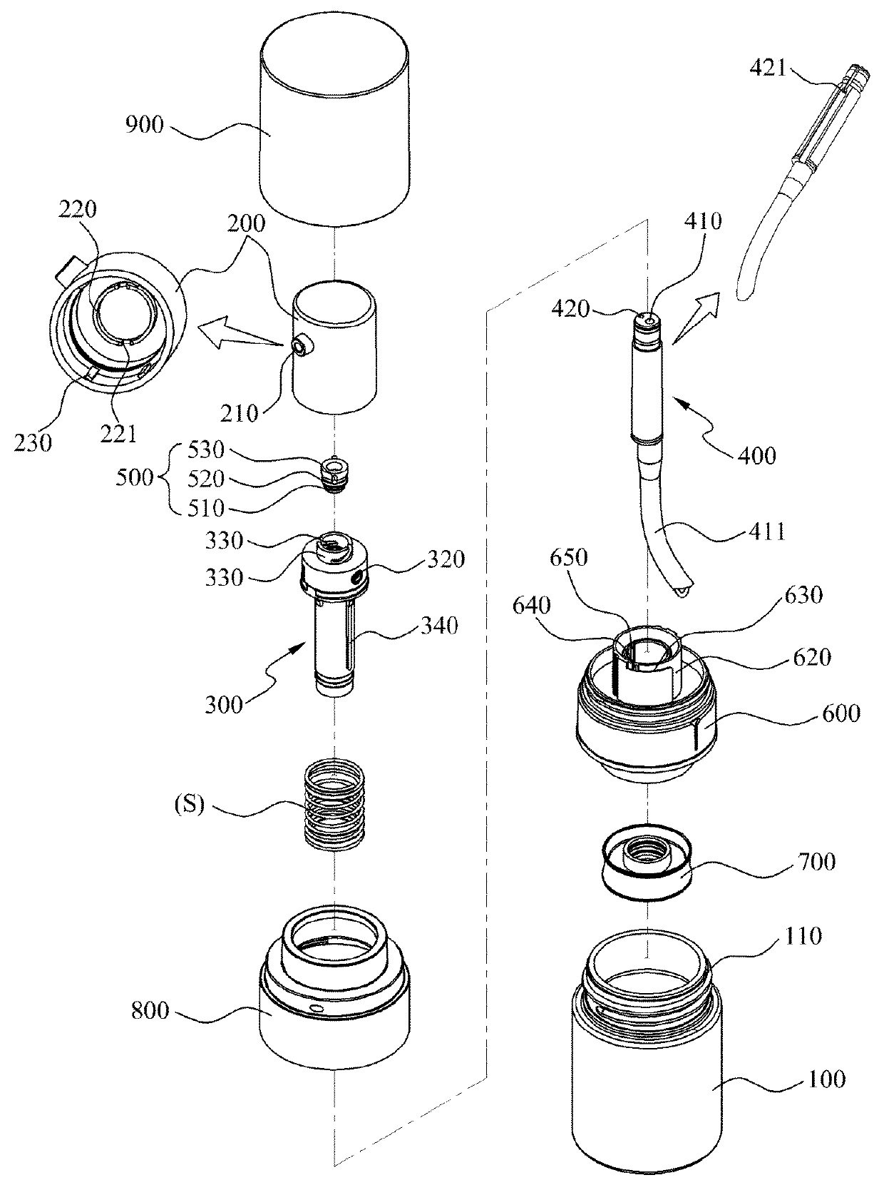
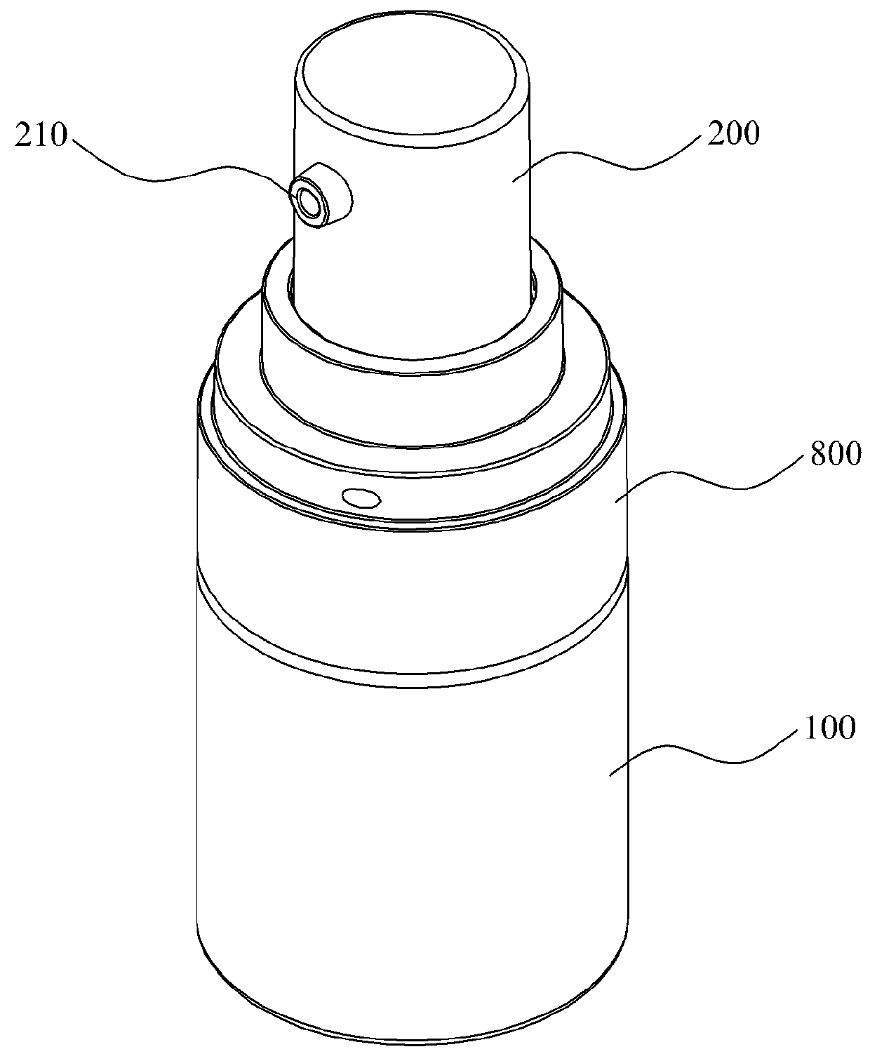
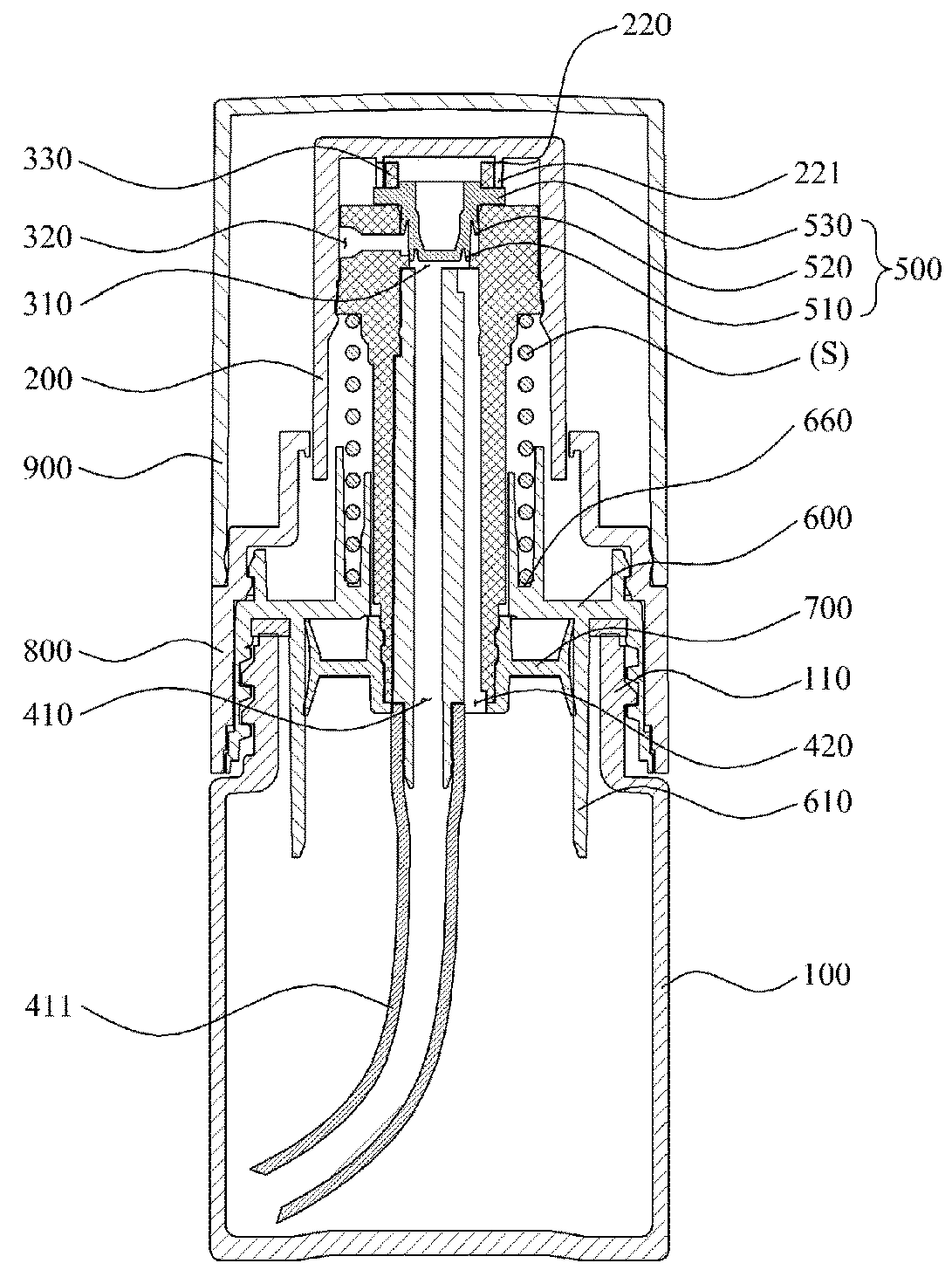
[0032]FIG. 1 is an exploded perspective view illustrating a configuration of a container for discharging powder according to an exemplary embodiment. FIG. 2 is a combined perspective view illustrating a configuration of the container for discharging powder according to an exemplary embodiment. FIG. 3 is a combined cross-sectional view illustrating a configuration of the container for discharging powder according to an exemplary embodiment.

[0033]FIG. 4(a) to FIG. 4(b) is an explanatory drawing illustrating a position of a pumping guide protrusion depending on the rotation of a button part of the container for discharging powder according to an exemplary embodiment. FIG. 5 is an explanatory drawing illustrating coupling state of a rotation preventing protrusion of a stem and a rotation preventin...


PUM


Abstract

The present invention disclosed herein relates to a container for discharging powder, in particular, a container for discharging powder having a structure wherein a discharging hole of a button part and a connecting hole of a stem are connected or dislocated according to rotation directions, and an opening/closing member is inserted into the stem inside the button part and ascends/descends according to a rotation of the button part, and thereby opens/closes a movement hole of the stem, such that it will solve inconvenience problems such as attaching/detaching the opening/closing member whenever using as well as prevent a risk of losing the opening/closing member, thereby providing user convenience.

Description

TECHNICAL FIELD[0001]The present disclosure relates to a container for discharging powder, in particular, a container for discharging powder having a structure wherein a discharging hole of a button part and a connecting hole of a stem are connected or dislocated according to rotation directions, and an opening / closing member is inserted into the stem inside the button part and ascends / descends according to a rotation of the button part, thereby opening / closing a movement hole of the stem, such that it will solve inconvenience problems such as having to attach / detach the opening / closing member whenever using as well as prevent a risk of losing the opening / closing member, thereby providing user convenience.BACKGROUND[0002]Generally, power has its good wearability when applied on skin, and has its high water-repellency, such that power is widely being used because a user feels fresh on the skin and gets her makeup to look natural.[0003]When applying a power-type makeup, a user usually...

Claims


Application Information

Patent Timeline
Patent Type & Authority Applications(United States)
IPC IPC(8): B05B11/06B05B11/00B65D83/06A45D33/02
CPCB05B11/062B05B11/3059B65D83/06A45D33/02A45D33/08B05B11/0029B05B11/0032B65D47/00B65D83/0005A45D2033/001B05B11/1059
Inventor JUNG, SEO-HUIHAM, KI-YOUNG
Owner YONWOO CO LTD
Why Eureka
Try Eureka