Unlock instant, AI-driven research and patent intelligence for your innovation.

Autonomous driving system

a technology of autonomous driving and driving system, which is applied in the direction of vehicle position/course/altitude control, process and machine control, instruments, etc., can solve the problems of driver not yet reaching the stage of being able to judge the necessity of travel control, driver feels sense of strangeness and anxiety, and decreases so as to reduce driver's sense of strangeness and anxiety, and increase the confidence of the autonomous driving system

Active Publication Date: 2018-06-28
TOYOTA JIDOSHA KK
View PDF2 Cites 8 Cited by
  • Summary
  • Abstract
  • Description
  • Claims
  • Application Information

AI Technical Summary

Benefits of technology

The patent is about a technique that helps reduce a driver's anxiety and discomfort when an autonomous driving system proposes or controls travel. The system estimates when the driver can visually recognize an event in front and proposes or executes travel control to change the vehicle's position based on that event. This reduces the driver's feeling of strangeness and anxiety, making them more confident in the autonomous driving system.

Problems solved by technology

Therefore, even when the autonomous driving system recognizes an event existing in front of the vehicle, it is highly probable that the driver has not yet recognized the event.
Moreover, even when the autonomous driving system proposes or executes travel control addressing the event, it is highly probable that the driver has not yet reached a stage of being able to judge necessity of the travel control.
Therefore, if the travel control is proposed or executed at a timing determined by the autonomous driving system, the driver feels senses of strangeness and anxiety.
This causes decrease in confidence m the autonomous driving system.
The delay time increases as the number of surrounding vehicles becomes larger.

Method used


Image

  • Autonomous driving system
  • Autonomous driving system
  • Autonomous driving system

Examples


first example

4-2-1. FIRST EXAMPLE

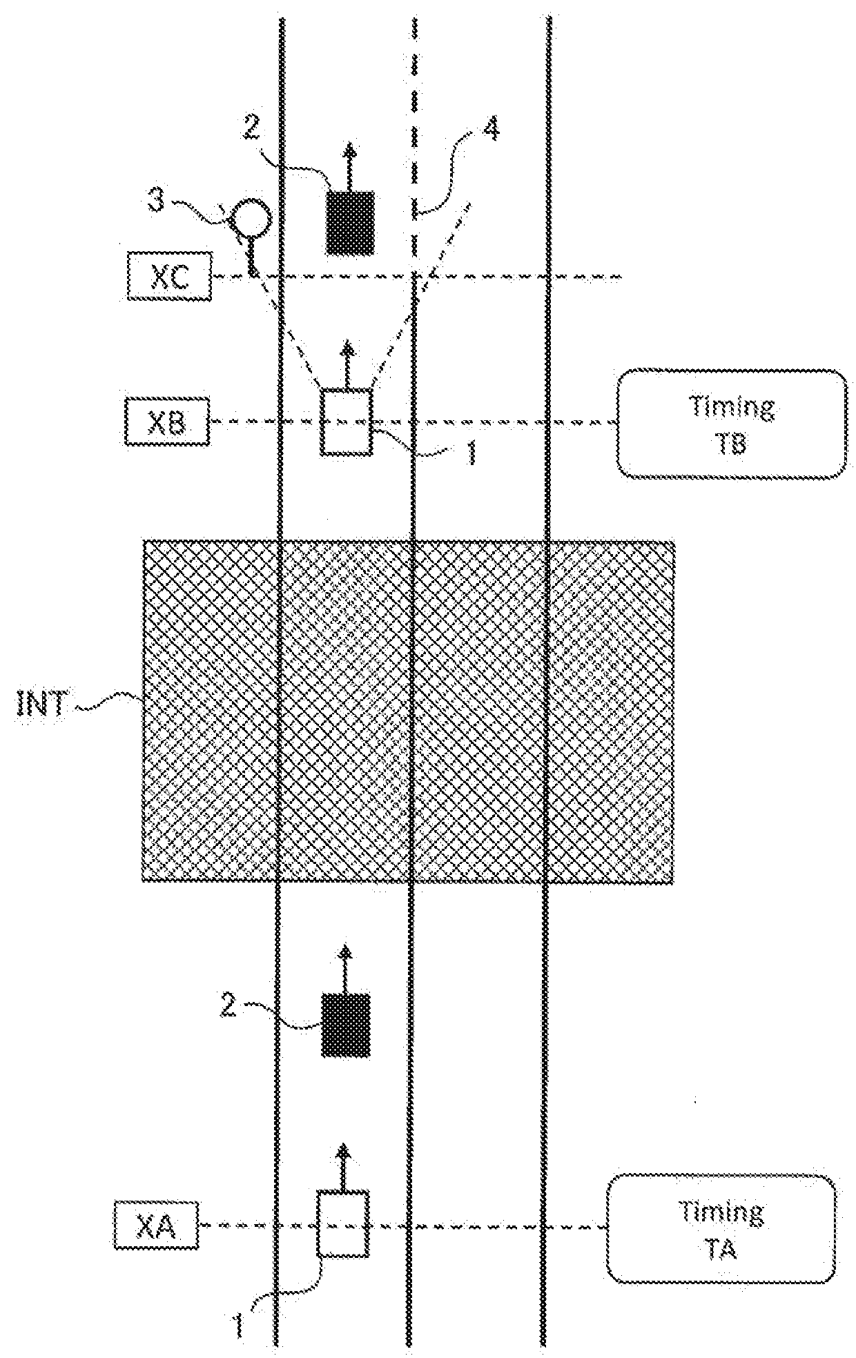
[0097]In the example shown in FIG. 1, the traffic sign 3 and the change in lane marking 4 each indicates a change in traffic rule. The driver of the vehicle 1 recognizes the change in traffic rule by finding (i.e. visually-recognizing) the traffic sign 3 or the change in lane marking 4.

[0098]Meanwhile, the autonomous driving system 100 is provided with the camera 30C that optically images a situation around the vehicle 1. By performing an image analysis of the image information 83C imaged by the camera 30C, it is possible to recognize the traffic sign 3 and the change in lane marking 4. That is to say, the camera 30C of the autonomous driving system 100 is equivalent to eyes of the driver. Therefore, a timing at which the traffic sign 3 or the change in lane marking 4 is recognized based on the image information 83C is considered to be close to the visually-recognizing timing TB of the driver.

[0099]To further generalize the above viewpoint, let us define a term “...

second example

4-2-2. SECOND EXAMPLE

[0101]Although the autonomous driving system 100 is capable of recognizing a lot of targets at a time, the driver cannot recognize a lot of targets at a time. In some cases, the driver looks in a direction different from the forward event. Due to these reasons, the visually-recognizing timing TB tends to be delayed from the above-described first timing. Therefore, in the second example, a timing after the first timing is set (estimated) as the visually-recognizing timing TB.

[0102]FIG. 8 is a flow chart showing the visually-recognizing timing estimation processing (Step S20) according to the second example. The visually-recognizing timing estimation unit 73 first recognizes the item indicating the forward event based on the image information 83C (Step S21). This Step S21 is the same as in the case of the above-described first example.

[0103]Subsequently, the visually-recognizing timing estimation unit 73 obtains a delay time (Step S22). For example, the delay time...

third example

4-2-3. THIRD EXAMPLE

[0105]In a third example, the delay time from the first timing to the visually-recognizing timing TB is not constant but variably set. As an example, let us consider a case where there is a lot of surrounding vehicles around the vehicle 1. In this case, there is a possibility that the driver is distracted by the surrounding vehicles and thus the timing to find the item is delayed. That is to say, the driving environment for the vehicle 1 affects the visually-recognizing timing TB. From this viewpoint, in the third example, the visually-recognizing timing estimation unit 73 variably sets the delay time in the above-described Step S22 according to the driving environment. As a result, the accuracy of the visually-recognizing timing estimation processing is further improved.

[0106]FIG. 9 is a block diagram for explaining the visually-recognizing timing estimation processing (Step S20) according to the third example. The visually-recognizing timing estimation unit 73 ...


PUM


Abstract

An autonomous driving system has: an information acquisition device configured to acquire driving environment information indicating driving environment for a vehicle; and an autonomous driving control device configured to control autonomous driving of the vehicle based on the driving environment information. A forward event is an event that exists in front of the vehicle and causes the autonomous driving control device to change a travel state of the vehicle. The autonomous driving control device performs: event detection processing that detects the forward event based on the driving environment information; visually-recognizing timing estimation processing that estimates a visually-recognizing timing at which a driver of the vehicle is able to visually-recognize the forward event; and travel control processing that proposes or executes, at or after the visually-recognizing timing, travel control that changes the travel state according to the forward event.

Description

CROSS-REFERENCE TO RELATED APPLICATIONS[0001]This application claims priority to Japanese Patent Application No. 2016-249578 filed on Dec. 22, 2016, which is incorporated herein by reference in its entirety include the specification, drawings and abstract.BACKGROUNDTechnical Field[0002]The present disclosure relates to an autonomous driving technique for a vehicle. In particular, the present disclosure relates to proposal and execution of travel control by an autonomous driving system.Background Art[0003]Patent Literature 1 discloses a technique regarding zone driving by an autonomous driving system. In the technique, a roadgraph includes a zone associated with a particular rule. When a vehicle approaches the zone, the autonomous driving system alerts a driver that the vehicle is approaching the zone, and requires the driver to take control (steering, acceleration, deceleration, and the like) according to the particular rule.List of Related Art[0004]Patent Literature 1: Japanese Tra...

Claims


Application Information

Patent Timeline
IPC IPC(8): G05D1/02G05D1/00G06K9/00G08G1/0967
CPCG05D1/0246G05D1/0088G06K9/00798G06K9/00825G08G1/0967G08G1/096725G06V20/588G06V20/584
Inventor HASHIMOTO, RYUTAWATANABE, YOSHINORI
Owner TOYOTA JIDOSHA KK