Thermoelectric conversion module

a technology of conversion module and thermal insulation layer, which is applied in the direction of basic electric elements, semiconductor devices, material nanotechnology, etc., can solve the problems of increasing the cost of insulating substrate in the entire, increasing and reducing the use amount of insulating substrate directly, so as to achieve high power generation output

Inactive Publication Date: 2018-06-28
FUJIFILM CORP
View PDF4 Cites 1 Cited by
  • Summary
  • Abstract
  • Description
  • Claims
  • Application Information

AI Technical Summary

Benefits of technology

[0028]According to the present invention, it is possible to obtain a thermoelectric conversion module which exhibits high power generation output.

Problems solved by technology

In addition, due to a decrease in the manufacturing cost, the percentage of the cost of the insulating substrate in the entire cost of the thermoelectric conversion element is increased and thus a decrease in the usage amount of the insulating substrate directly contributes to a decrease in the cost of the thermoelectric conversion element.
As a result, the power generation amount is significantly decreased.
In a case where the insulating layer is arranged between the thermoelectric conversion elements as described above, the insulating layer functions as a heat conductive medium and thus there is a problem of decreasing a temperature difference between the thermoelectric conversion elements.
However, compared to a state in which the insulating substrates are overlapped, the heat transfer area is significantly increased and thus there is a problem of decreasing power generation output density, that is, decreasing the power generation amount per unit heat transfer area.

Method used


Image

  • Thermoelectric conversion module
  • Thermoelectric conversion module
  • Thermoelectric conversion module

Examples


Embodiment Construction

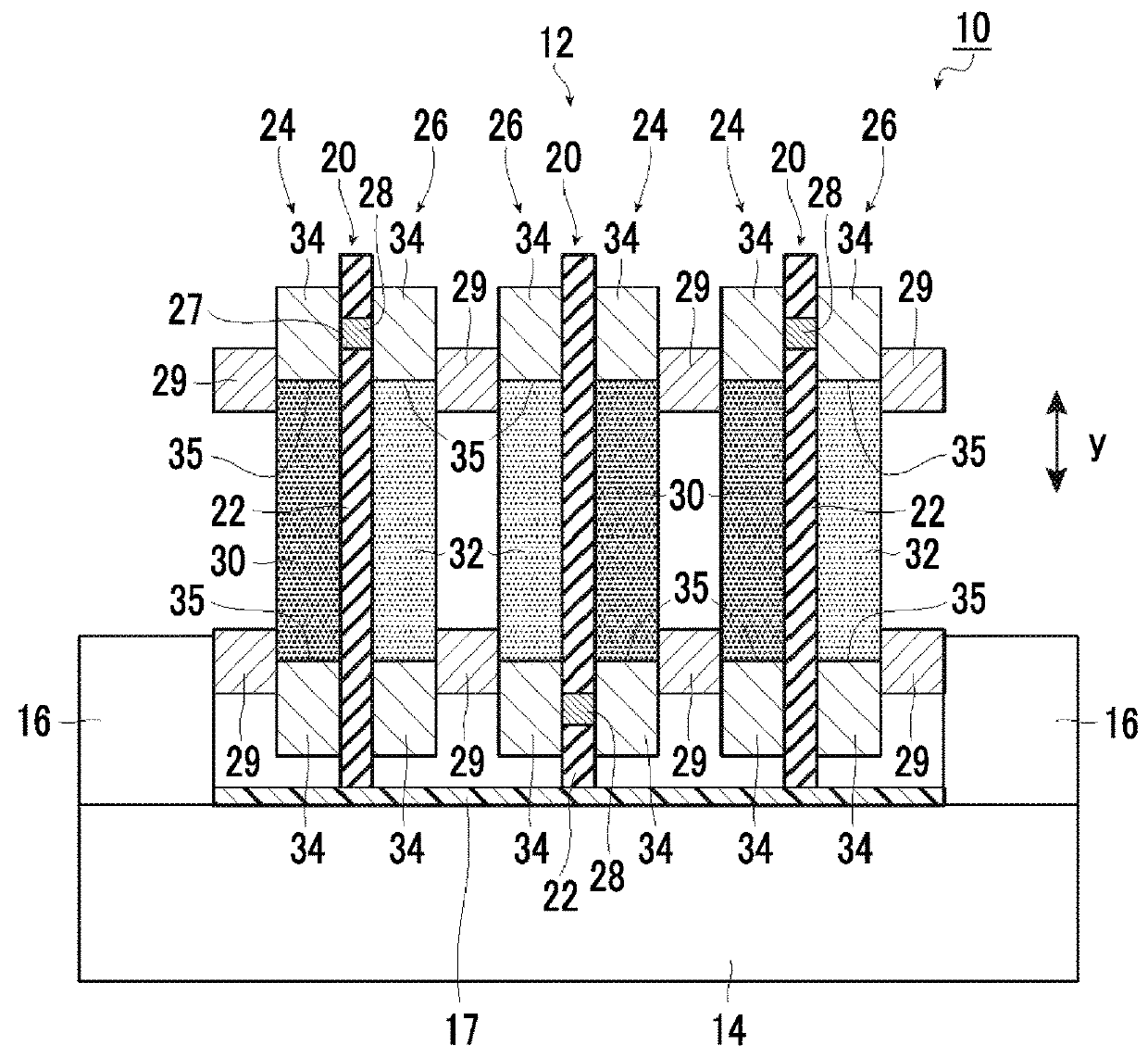
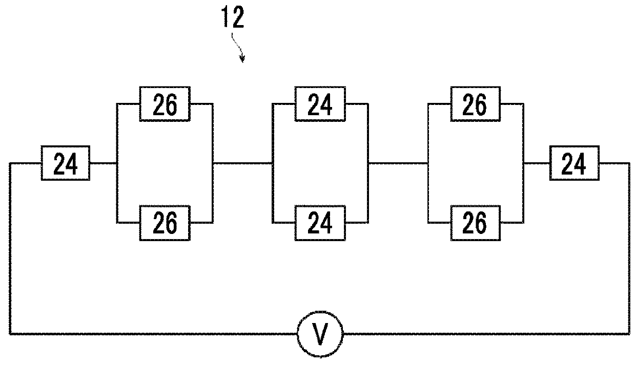
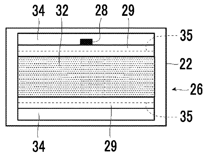
[0039]Hereinafter, a thermoelectric conversion module of the present invention will be described in detail based on preferable embodiments shown in the accompanying drawings.

[0040]In the following description, “to” indicating a numerical value range includes numerical values described on both sides. For example, when ε is a numerical value α to a numerical value β, the range of ε is a range including the numerical value α and the numerical value β, and is represented as α≤ε≤β using mathematical symbols.

[0041]Unless otherwise specified, an angle means that a difference from the exact angle falls within a range of less than 5°. The difference from the exact angle is preferably less than 4° and more preferably less than 3°.

[0042]The meaning of “the same” includes an error range that is generally allowable in the technical field. In addition, the meaning of “entire surface” and the like includes not only 100% but also a case where an error range is generally allowable in the technical f...


PUM


Abstract

The present invention addresses the problem of providing a thermoelectric conversion module which suppresses a decrease in a power generation amount and exhibits high power output. The thermoelectric conversion module includes a thermoelectric conversion module substrate in which a P-type thermoelectric conversion element having a P-type thermoelectric conversion layer and a pair of connection electrodes, which are electrically connected to the P-type thermoelectric conversion layer, is provided on at least one surface of an insulating substrate, and an N-type thermoelectric conversion element having an N-type thermoelectric conversion layer and a pair of connection electrodes, which are electrically connected to the N-type thermoelectric conversion layer, is provided at least the other surface of the insulating substrate. The connection electrodes formed on the one surface of the insulating substrate and the connection electrodes formed on the other surface of the insulating substrate opposite to the one surface are electrically connected to each other, or a plurality of the thermoelectric conversion module substrates are laminated by being connected to each other through the connection electrodes.

Description

CROSS-REFERENCE TO RELATED APPLICATIONS[0001]This application is a Continuation of PCT International Application No. PCT / JP2016 / 075077 filed on Aug. 26, 2016, which claims priority under 35 U.S.C. § 119(a) to Japanese Patent Application No. 2015-170816 filed on Aug. 31, 2015 and Japanese Patent Application No. 2016-108743 filed on May 31, 2016. Each of the above applications is hereby expressly incorporated by reference, in its entirety, into the present application.BACKGROUND OF THE INVENTION1. Field of the Invention[0002]The present invention relates to a thermoelectric conversion module in which thermoelectric conversion elements are provided on both surfaces of an insulating substrate, and particularly relates to a thermoelectric conversion module exhibiting high power generation output.2. Description of the Related Art[0003]Thermoelectric conversion materials that can mutually convert thermal energy and electric energy are used in power generating elements that generate power b...

Claims


Application Information

Patent Timeline
Patent Type & Authority Applications(United States)
IPC IPC(8): H02N11/00H01L23/48H01L23/14H01L23/52
CPCH02N11/002H01L23/48H01L23/14H01L23/52B82Y30/00H10N10/855H10N10/856H10N10/17
Inventor SUZUKI, HIDEYUKIIMAI, SHINJI
Owner FUJIFILM CORP
Why Eureka
Try Eureka