Phase change coupling bionic fin type automobile exhaust waste heat cascade power generation system

A bionic fin type, automobile exhaust technology, applied in the directions of generators/motors, exhaust devices, electrical components, etc., can solve the problems of no automobile exhaust heat utilization, cold end heat loss, low power generation efficiency, etc., to prevent heat The effect of greatly changing the terminal temperature, preventing local temperature overheating, and improving the utilization rate

Active Publication Date: 2020-08-28
XI AN JIAOTONG UNIV
View PDF4 Cites 0 Cited by
  • Summary
  • Abstract
  • Description
  • Claims
  • Application Information

AI Technical Summary

Problems solved by technology

[0006] At present, there are some automobile exhaust power generation systems on the market, but unfortunately, these power generation systems all have low power generation efficiency and are huge in size
Most of similar systems use water cooling for heat dissipation at the cold end, which has a complex structure, high manufacturing cost, and low reliability; moreover, there is a lot of heat loss at the cold end, which does not effectively utilize the heat of automobile exhaust

Method used


Image

  • Phase change coupling bionic fin type automobile exhaust waste heat cascade power generation system
  • Phase change coupling bionic fin type automobile exhaust waste heat cascade power generation system
  • Phase change coupling bionic fin type automobile exhaust waste heat cascade power generation system

Examples


Embodiment Construction

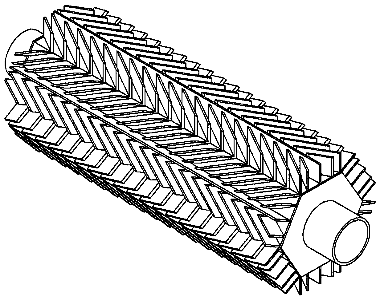
[0032] In order to further illustrate the working principle of the system of the present invention, the system is further described in conjunction with the accompanying drawings.

[0033] Such as figure 1 As shown, the present invention is a phase-change coupling bionic fin type automobile exhaust waste heat cascade power generation system, which mainly includes an inner heat conduction structure, a middle semiconductor thermoelectric power generation module and an outer fin radiator.

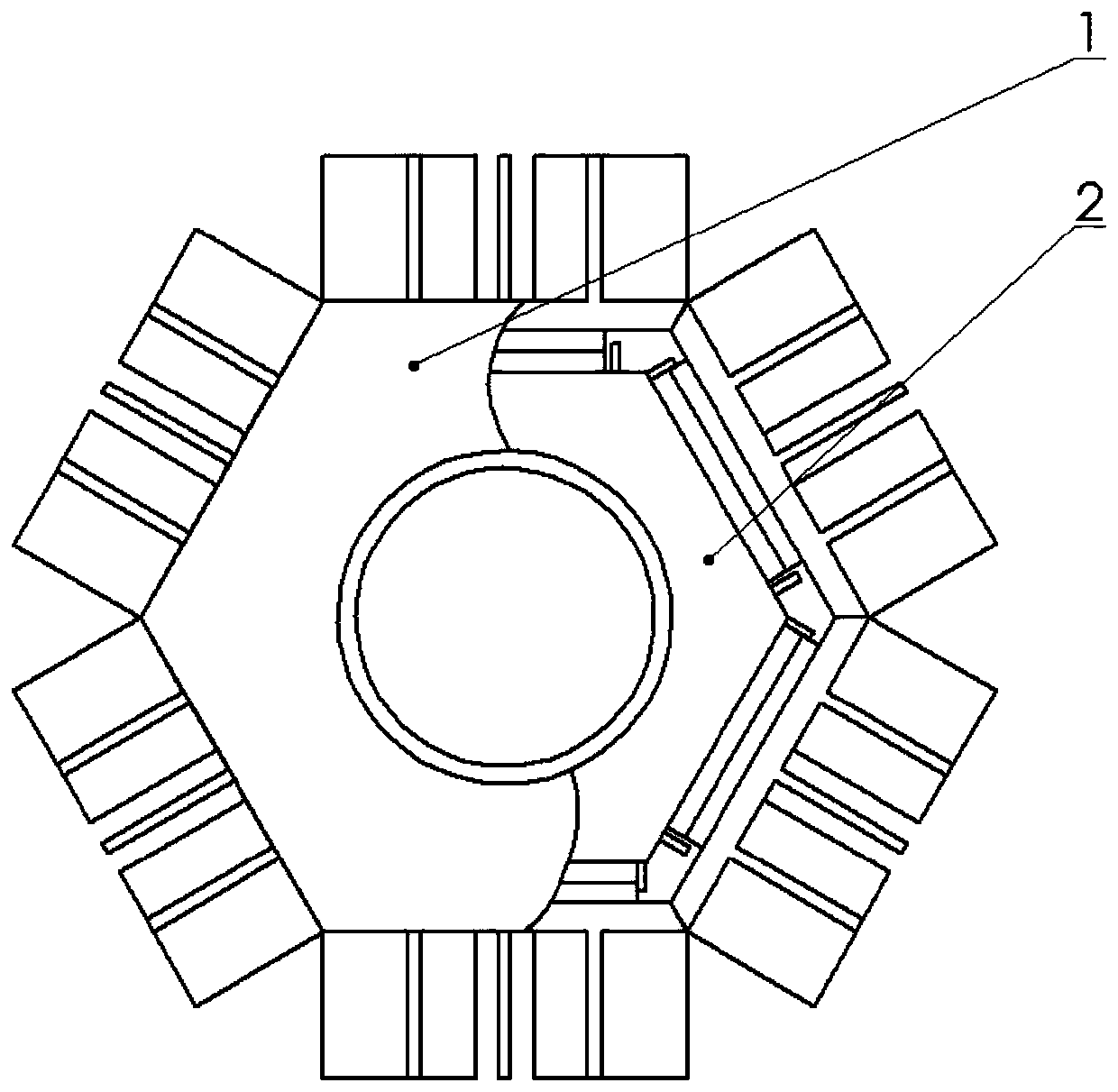
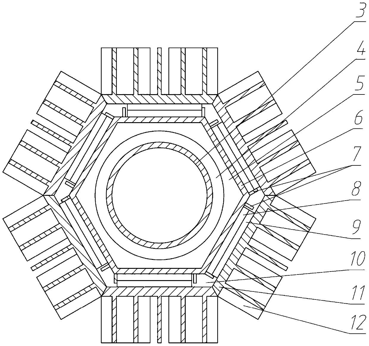
[0034] Specifically, refer to figure 2 and image 3 , the inner heat conduction structure includes a coaxial cylindrical inner wall 3 and an inner casing 6, the inner side of the cylindrical inner wall 3 is in close contact with the outer wall of the vehicle exhaust pipe, and an automobile exhaust pipe with an outer diameter of 51mm is selected for installation and arrangement, for The inner wall 3 is closely attached to it, and the inner diameter of the cylindrical inner wall 3 is selected ...


PUM


Abstract

The invention relates to a phase-change coupling bionic fin type automobile exhaust waste heat step power generation system. The system comprises an inner layer heat conduction structure, a middle semiconductor temperature difference power generation module and an outer layer fin radiator. The inner layer heat conduction structure is tightly attached to the outer wall of an exhaust pipe of an automobile, and the whole body of the inner layer heat conduction structure is in a hexagonal prism shape so as to supply a flat attachment point for the temperature difference power generation module; the heat conduction structure is filled with phase-change material fused salts so that the temperature of the outer wall of the heat conduction structure is uniform and constant and the heat in the automobile exhaust waste is accumulated. The middle semiconductor temperature difference power generation module employs a dual-layer design, the inner layer power generation module and the outer layer power generation module select different thermoelectric materials according to respective actual working temperature areas, and the optimal working temperature areas of the two power generation modulesare matched with the actual temperature areas of the two power generation modules so that the two layers of power generation modules work at the optimal temperature, and the cascade utilization of theautomobile exhaust waste heat is achieved. The outer layer fin radiator adopts a leaf-shaped bionic structure, and forced convection heat dissipation is performed by utilizing air flow generated whenan automobile runs. The automobile exhaust can be used for generating power, and the waste heat utilization of the exhaust is achieved.

Description

technical field [0001] The invention belongs to the technical field of auto parts, and in particular relates to a phase change coupled bionic fin type automobile exhaust waste heat cascade power generation system. Background technique [0002] The automobile industry is one of the pillar industries of my country's national economy. With the development of my country's automobile industry, the energy saving of vehicles has attracted more and more attention. However, more than 60% of the energy in the fuel consumed by the internal combustion engine has not been effectively utilized, and most of the energy is discharged into the atmosphere in the form of waste heat from automobile exhaust, causing huge economic losses and energy waste. If this part of energy is recycled reasonably, the fuel consumption of the car can be greatly saved, and the goal of energy saving and emission reduction can be achieved at the same time, which has good social and economic benefits. [0003] Th...

Claims


Application Information

Patent Timeline
Patent Type & Authority Patents(China)
IPC IPC(8): H02N11/00F01N5/02
CPCF01N5/025H02N11/002Y02T10/12
Inventor 何雅玲童俊代明昊吕方为谷鑫赵春雨王文奇
Owner XI AN JIAOTONG UNIV
Why Eureka
Try Eureka