Physiological monitoring garments with enhanced sensor stabilization

Inactive Publication Date: 2018-07-05
L I F E
View PDF0 Cites 55 Cited by
  • Summary
  • Abstract
  • Description
  • Claims
  • Application Information

AI Technical Summary

Benefits of technology

[0038]The sensing components of the extended-wear monitoring garment may either be integrated into the extended-wear monitoring garment or the monitoring components may be removed in part or in whole. In the former case, it would especially desirable to minimize the need for washing/laundering the extended-wear monitoring garment, such that the sensing components are minimally exposed to damaging moisture and cleaning agents. In the latter case, where it may be possible to remove the sensors or a portion of the sensor module prior to laundering, this would help to extend the life of the extended-wear monitoring garment. In this latter case, it would still be preferable to extend the wear-ability of the extended-wear monitoring garment because some electrical component, such as the conductive ink traces, remain integrated in the extended-wear monitoring garment.
[0039]In order to minimize the amount of laundering required of an ex

Problems solved by technology

Unfortunately, most currently available cardiovascular and other types of health monitoring systems are cumbersome and inconvenient (e.g., impractical for everyday use) and in particular, are difficult or impractical to use for long-term monitoring, particularly in an unobtrusive manner
It has been proposed that patient health parameters, including vital signs (such as ECG, respiration, blood oxygenation, heart rate, etc.) could be actively monitoring using one or more wearable monitors, however, to date such monitors have proven difficult to use and relatively inaccurate.
Ideally such monitors could be unobtrusively worn by the subject (e.g., as part of a garment, jewelry, or the like).
Although such garments have been proposed, see, e.g., US 2012/0136231, these garments suffer from a number of deficits, including being uncomfortable, difficult to use, and providing inaccurate results.
Such a configuration rapidly becomes uncomfortable, particularly in a garment that would ideally be worn for many hours or even days.
In addition, even such tightly worn garments often move relative to

Method used


Image

  • Physiological monitoring garments with enhanced sensor stabilization
  • Physiological monitoring garments with enhanced sensor stabilization
  • Physiological monitoring garments with enhanced sensor stabilization

Examples


examples

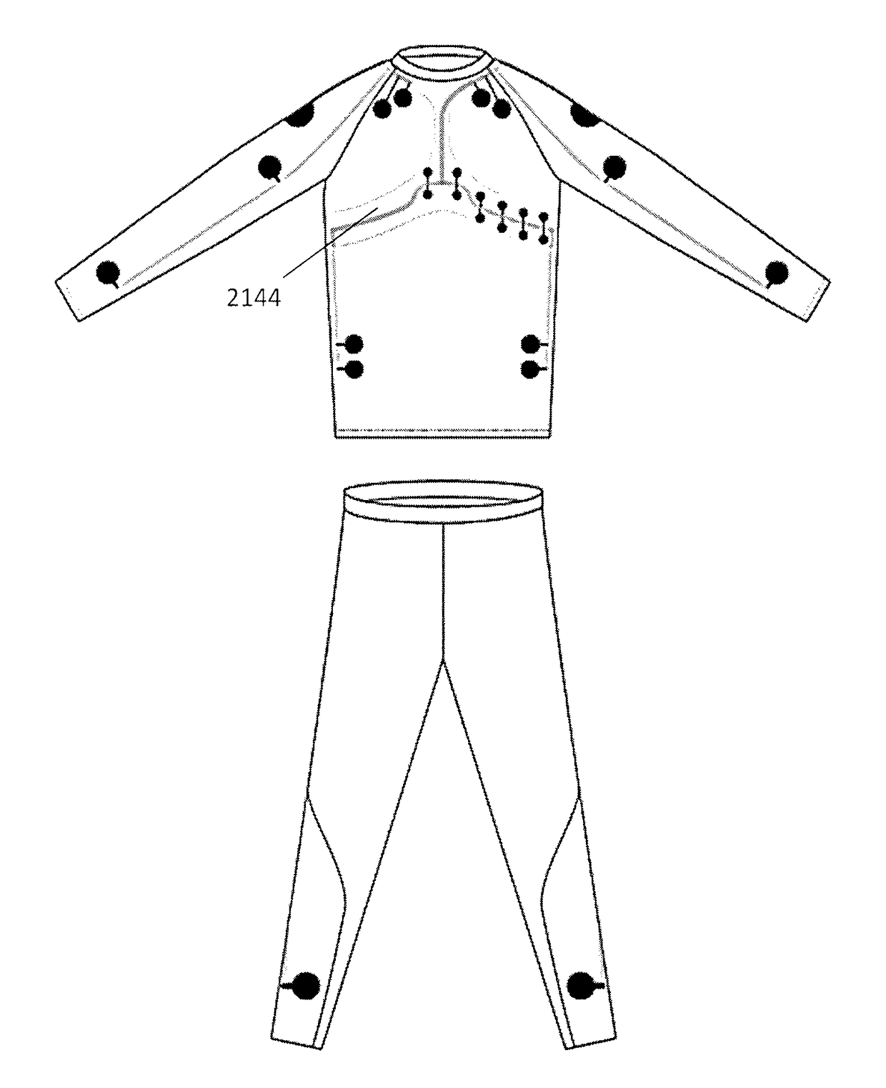
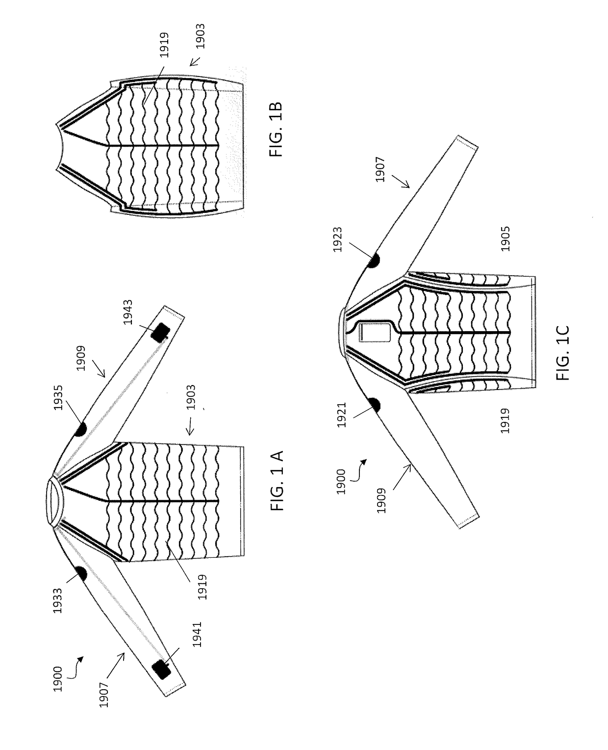
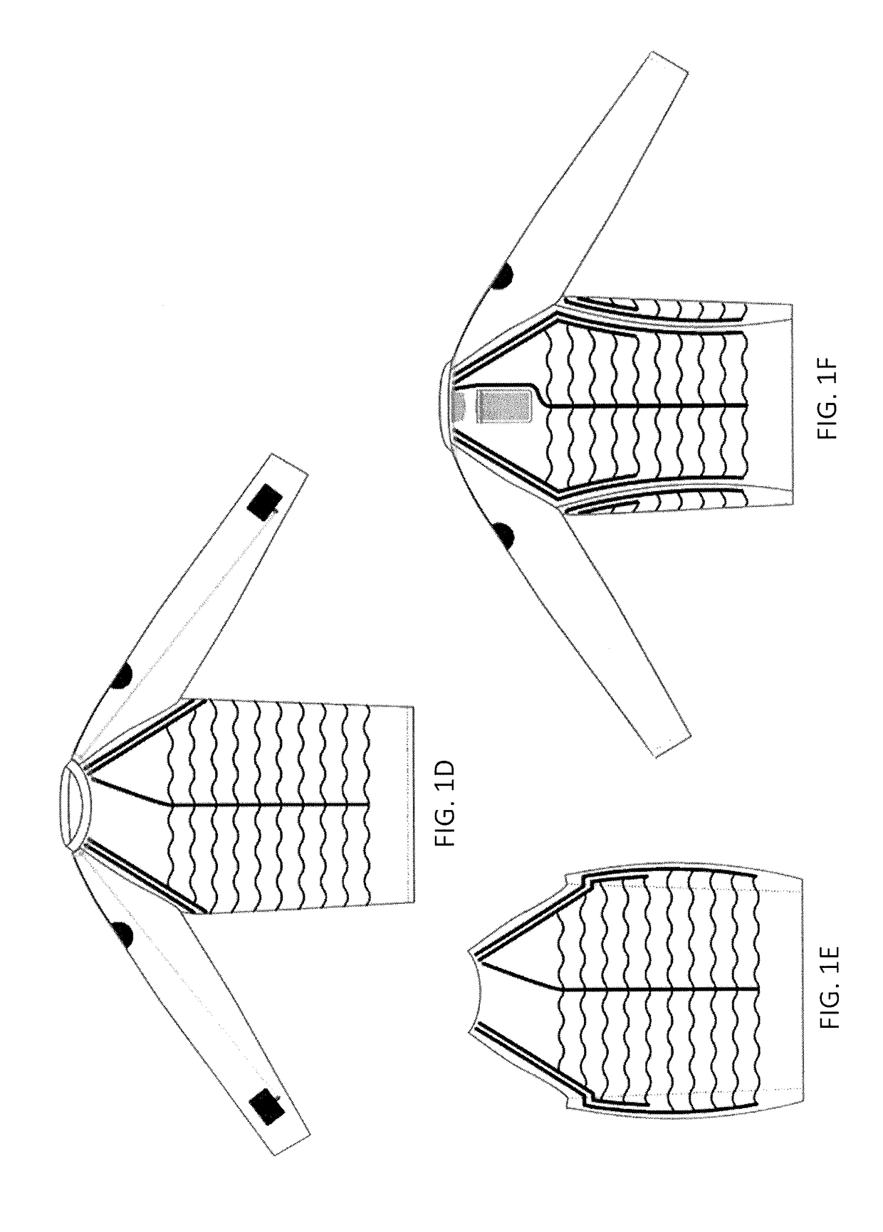
[0296]FIGS. 29A-29B and 30A-30B show another example of a garment as described herein, similar to that shown above in FIGS. 26A and 26B. In FIGS. 29A-29B and 30A-30B the garment is configured to detect both respiration and cardiac output (such as an electrocardiograph, ECG). Any of the sensors described herein may be included. In any of these garments, the apparatus may include a side-opening, a front opening or a back opening and fastener, such as a zipper or Velcro closure (not shown in FIG. 30A-30B). Chest electrodes 2905 (corresponding to and labeled as leads V1-V6) are arranged across the chest portion of the garment so that they may be positioned against the traditional positions of the wearers chest when the garment is worn. Right and left arm electrodes (RA, LA) are also show on the arms. Straps 2909 can be integrated into the garment (e.g., beneath the outer layer and / or between an inner and the outer layer), e.g., on the arms and across the chest and back 2909′ and / or wais...


PUM


Abstract

Described herein are apparatuses (e.g., garments, including but not limited to shirts, pants, and the like) for detecting and monitoring physiological parameters, such as respiration, cardiac parameters, and the like that include individual skin contact-enhancing expandable elements.

Description

CROSS REFERENCE TO RELATED APPLICATIONS[0001]This patent application claims priority as a continuation-in-part to International Patent Application No. PCT / IB2016 / 001319, titled “PHYSIOLOGICAL MONITORING GARMENTS WITH ENHANCED SENSOR STABILIZATION,” filed on Aug. 24, 2016, now International Patent Application Publication No. WO 2017 / 033058, which claims priority to U.S. Provisional Patent Application No. 62 / 209,034, titled “PHYSIOLOGICAL MONITORING GARMENTS WITH ENHANCED SENSOR STABILIZATION,” filed on Aug. 24, 2015, and U.S. Provisional Patent Application No. 62 / 233,693, titled “PHYSIOLOGICAL MONITORING GARMENTS WITH ENHANCED SENSOR STABILIZATION,” filed on Sep. 29, 2015, each of which are herein incorporated by reference in its entirety.[0002]This application may be related to U.S. patent application Ser. No. 15 / 877378, titled “FLEXIBLE FABRIC RIBBON CONNECTORS FOR GARMENTS WITH SENSORS AND ELECTRONICS,” filed on Jan. 22, 2018, and to U.S. patent application Ser. No. 14 / 644,180, fi...

Claims


Application Information

Patent Timeline
IPC IPC(8): A41D13/12A41B1/08A41D1/00A41D1/06A63B24/00A61B5/0408A61B5/00A61B5/11
CPCA41D13/1281A41B1/08A41D1/005A41D1/06A63B24/0062A61B5/04085A61B5/6805A61B5/1123A63B2230/04A61B2562/0209A61B5/6831A61B5/6843A61B5/282
Inventor LONGINOTTI-BUITONI, GIANLUIGIALIVERTI, ANDREA
Owner L I F E
Why Eureka
Try Eureka