Toner bottle

a technology of toner and bottle, applied in the field of toner bottles, can solve the problems of wasting, wasting, and a large amount of toner left in the toner bottle, and achieve the effect of increasing the deflection amount and reducing the deflection amoun

Active Publication Date: 2018-07-05
MURATA MFG CO LTD
View PDF3 Cites 1 Cited by
  • Summary
  • Abstract
  • Description
  • Claims
  • Application Information

AI Technical Summary

Benefits of technology

[0012]When both ends of the toner bottle are supported, the sides of the bottle portion are deflected by self-weight or the weight of the toner. The deflection amount increases when a large amount of the toner remains in the bottle portion, and the deflection amount decreases when the toner decreases. Therefore, by providing the displacement sensor at the side of the bottle portion of the toner bottle to detect the deflection amount of the side of the bottle portion, it is possible to directly detect the remaining amount of the toner at the present time.

Problems solved by technology

When the toner in the development apparatus decreases, the toner cannot be supplied to the photoreceptor.
However, at the time of the notification, a substantial amount of the toner is usually remaining in the toner bottle.
Nevertheless, since the user needs to replace the toner with a new one, usable toner is thrown away and wasted.
Therefore, it is necessary to secure a space for the toner bottle 5 and the support member 52 to move, which consumes space and thus limits space saving.
However, the toner bottle has a weight of, for example, about 3 kg, and it becomes difficult to securely support the toner bottle if the number of support points is reduced.

Method used


Image

  • Toner bottle
  • Toner bottle
  • Toner bottle

Examples


Embodiment Construction

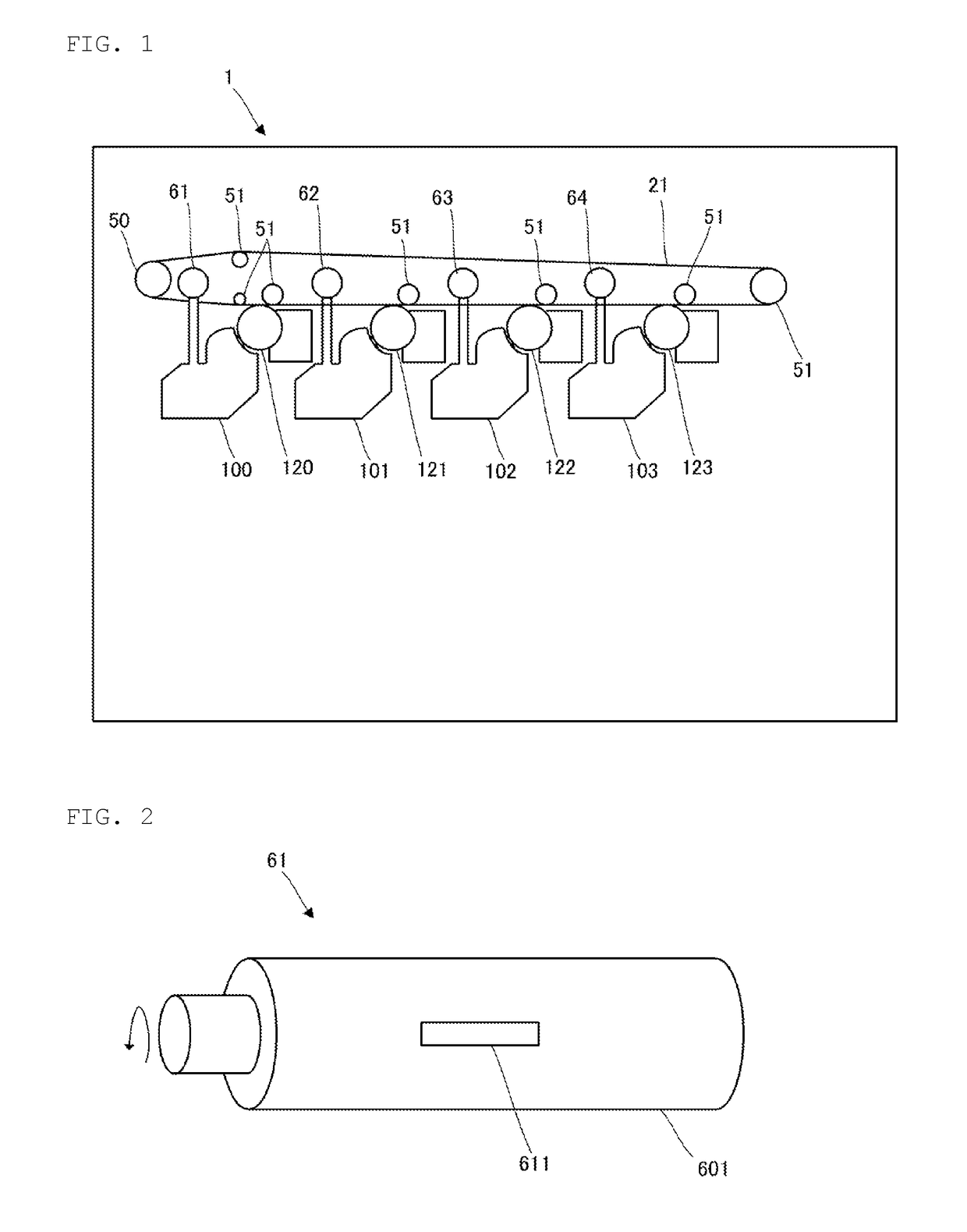
[0024]FIG. 1 is a schematic diagram showing a partial configuration of an image forming apparatus 1. The image forming apparatus 1 is configured to perform multicolor or monochrome electrophotographic image forming processing on a sheet based on image data inputted from an external apparatus (not shown).

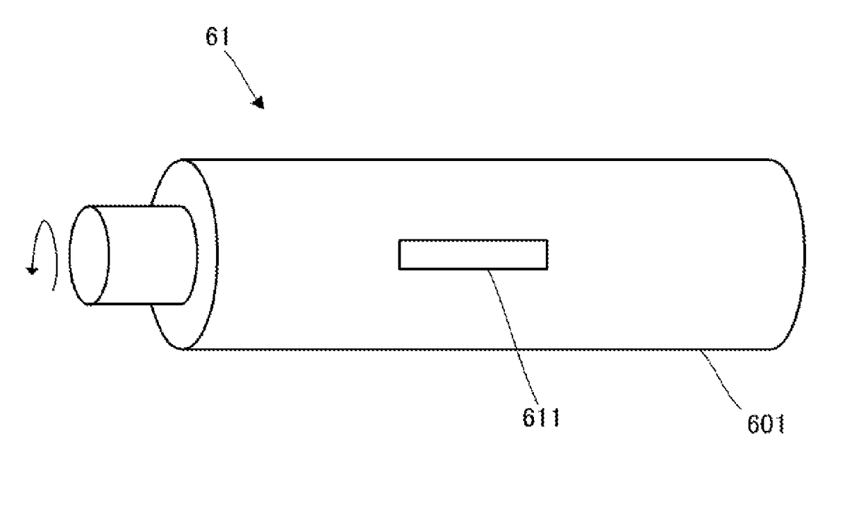
[0025]As shown, the image forming apparatus 1 includes a transfer belt 21, a drive roller 50, driven rollers 51, a development apparatus 100, a development apparatus 101, a development apparatus 102, a development apparatus 103, a photosensitive drum 120, a photosensitive drum 121, a photosensitive drum 122, a photosensitive drum 123, a toner bottle 61, a toner bottle 62, a toner bottle 63 and a toner bottle 64. In other words, the image forming apparatus 1 includes a plurality of development apparatuses 101-103, a plurality of photosensitive drums 120-123, and a plurality of toner bottles 61-64.

[0026]In an exemplary aspect, each of the photosensitive drum 120, the photosensitive dru...


PUM


Abstract

One or more toner bottles are provided for supplying toners to development apparatuses. The toner bottles each include bottle portions and displacement sensors. The bottle portions accommodate the toners and are rotated by a drive force of a drive source. The displacement sensors are positioned on sides of the bottle portions and detect deflection amounts of the sides of the bottle portions to determine how much toner is remaining in each toner bottle.

Description

CROSS REFERENCE TO RELATED APPLICATIONS[0001]The present application is a continuation of PCT / JP2016 / 081805 filed Oct. 27, 2016, which claims priority to Japanese Patent Application No. 2015-242152, filed Dec. 11, 2015, the entire contents of each of which are incorporated herein by reference.TECHNICAL FIELD[0002]The present disclosure relates to a toner bottle that accommodates toner.BACKGROUND[0003]Currently, image forming apparatuses form toner images by developing an electrostatic latent image formed on a photoreceptor by using toner in a development apparatus. When the toner in the development apparatus decreases, the toner cannot be supplied to the photoreceptor. Therefore, the image forming apparatus is configured so as to supply toner as appropriate to the development apparatus from a toner bottle attachable to the main body of the apparatus.[0004]The toner bottle includes a cylindrical casing, a spiral rib protruding on the inner peripheral surface of the casing, and an out...

Claims


Application Information

Patent Timeline
Patent Type & Authority Applications(United States)
IPC IPC(8): G03G15/08G01F23/00G01B7/16
CPCG03G15/0831G01F23/0069G01B7/16G03G15/087G01B7/18G03G2215/0663G03G15/086G03G15/0872G03G15/556G01F23/20G01F23/226G03G15/0856G01F23/802
Inventor ANDO, MASAMICHI
Owner MURATA MFG CO LTD
Why Eureka
Try Eureka