Optical deflector apparatus capable of increasing offset deflecting amount of mirror

an optical deflector and mirror technology, applied in the field of optical deflector apparatuses, can solve the problems of inability to increase the offset deflecting damage to the piezoelectric actuator, and inability to increase the rocking amount of the mirror, so as to achieve the effect of increasing the offset deflecting amount and increasing the rocking amoun

Active Publication Date: 2015-12-17
STANLEY ELECTRIC CO LTD
View PDF2 Cites 9 Cited by
  • Summary
  • Abstract
  • Description
  • Claims
  • Application Information

AI Technical Summary

Benefits of technology

[0012]According to the presently disclosed subject matter, since the first piezoelectric actuator for an offset operation mode is independent of the second piezoelectric actuator for a rocking operation mode, the offset deflecting amount (angle) can be increased, and also, the rocking amount (angle) can be increased.

Problems solved by technology

In the above-described prior art optical deflector apparatus, however, when the combined drive voltages become larger than a threshold value corresponding to the maximum rocking angle of the mirror with respect to the X-axis of the mirror, the piezoelectric actuators would be damaged.
As a result, the offset deflecting amount of the mirror cannot be increased.
In this case, it is impossible to increase the rocking amount of the mirror.

Method used


Image

  • Optical deflector apparatus capable of increasing offset deflecting amount of mirror
  • Optical deflector apparatus capable of increasing offset deflecting amount of mirror
  • Optical deflector apparatus capable of increasing offset deflecting amount of mirror

Examples


first embodiment

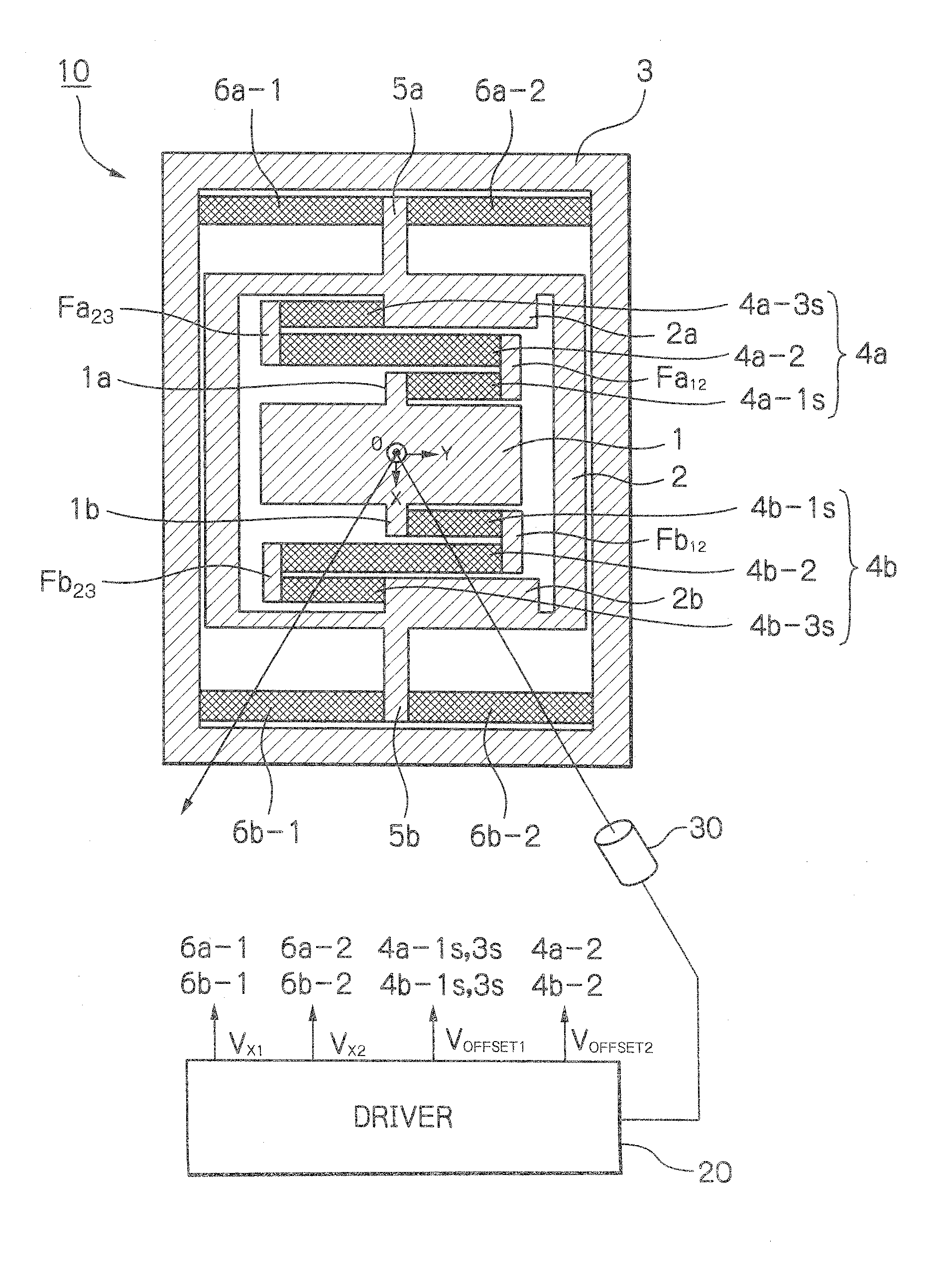
[0031]In FIG. 1, which illustrates the optical deflector apparatus according to the presently disclosed subject matter as a one-dimensional MEMS device, reference numeral 10 designates a one-dimensional optical deflector, 20 designates a driver for driving the optical deflector 10, and 30 designates a laser light source.

[0032]The optical deflector 10 is constructed by a rectangular mirror 1 for reflecting incident light L from the laser light source 30, a rectangular inner frame (movable frame) 2 surrounding the mirror 1, and a rectangular outer frame (fixed frame) surrounding the inner frame 2.

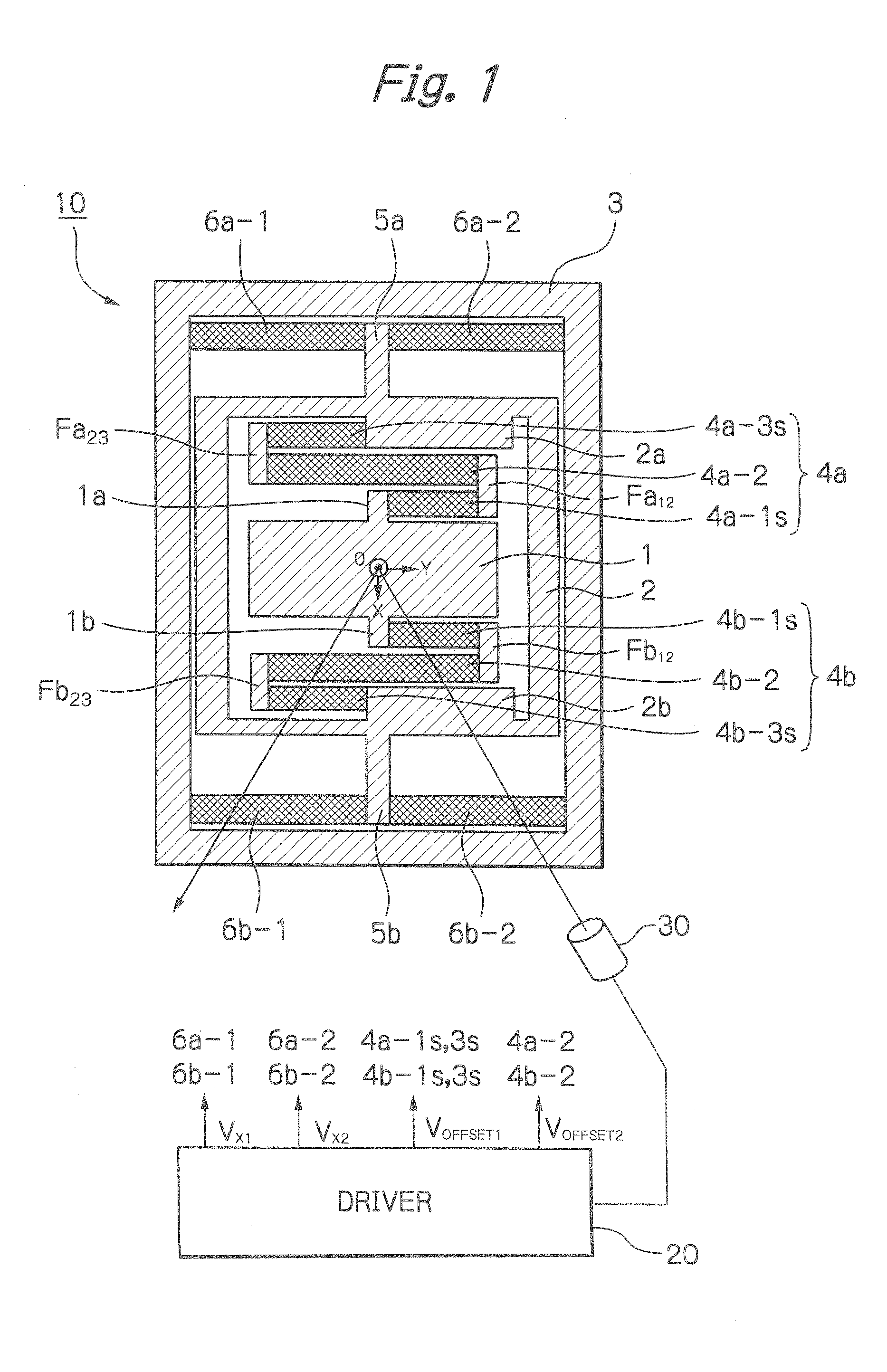
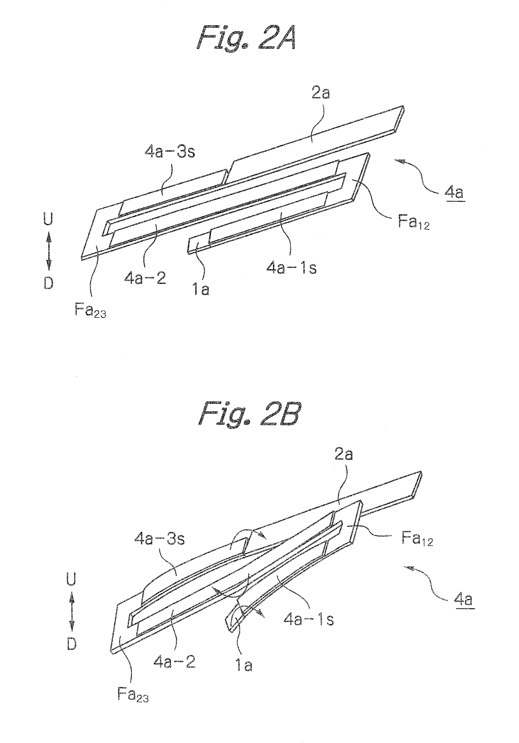
[0033]Also, in order to realize an offset operation mode, a pair of meander-type inner piezoelectric actuators 4a and 4b are coupled between coupling portions 1a and 1b of the mirror 1 and inner coupling portions 2a and 2b of the inner frame 2 and serving as cantilevers for rocking the mirror 1 around an X-axis on the plane of the mirror 1 centered at the center 0 of the mirror 1. The inner p...

second embodiment

[0068]In FIG. 6, which illustrates the optical deflector apparatus according to the presently disclosed subject matter, the torsion bars 5a and 5b and the outer piezoelectric actuators 6a-1, 6a-2, 6b-1 and 6b-2 of FIG. 1 are replaced by a pair of meander-type outer piezoelectric actuators 7a and 7b which are symmetrical to each other with respect to the Y-axis.

[0069]In more detail, the meander-type outer piezoelectric actuator 7a is constructed by piezoelectric cantilevers 7a-1s, 7a-2 and 7a-3s which are serially-coupled from a coupling portion 2c of the inner frame 2 to a coupling portion 3a of the outer frame 3 via folded portions Fc12 and Fc23. Also, each of the piezoelectric cantilevers 7a-1s, 7a-2 and 7a-3s is in parallel with the Y-axis. Therefore, the piezoelectric cantilevers 7a-1s, 7a-2 and 7a-3s are folded at their ends or meandering from the inner frame 2 to the outer frame 3 so that the amplitudes of the piezoelectric cantilevers 7a-1s, 7a-2 and 7a-3s can be changed alon...

third embodiment

[0084]In FIG. 14, which illustrates the optical deflector apparatus according to the presently disclosed subject matter as a two-dimensional MEMS device, reference numeral 100 designates a two-dimensional optical deflector, 200 designates a driver, and 300 designates a laser light source.

[0085]The optical deflector 100 includes the optical deflector 10 of FIG. 1. Additionally, in order to carry out another rocking operation mode around the Y-axis, the optical deflector 100 includes another outer frame (fixed frame) 101, a pair of torsion bars 102a and 102b coupled to the outer circumference of the outer frame 3 along the Y-axis, and linear outer piezoelectric actuators 103a-1 and 103a-2 coupled between the torsion bar 102a and the outer frame 101, and linear outer piezoelectric actuators 103b-1 and 103b-2 coupled between the torsion bar 102b and the outer frame 101. In this case, the outer frame 3 serves as a movable frame. The flexing direction of the outer piezoelectric actuators ...


PUM


Abstract

In an optical deflector apparatus including a mirror, an inner frame, an outer frame, an inner piezoelectric actuator adapted to flex the mirror around an axis of the mirror, an outer piezoelectric actuator adapted to flex the mirror around the axis of the mirror, and a driver adapted to generate an offset drive voltage and a rocking drive voltage. The offset drive voltage is applied to a first piezoelectric actuator selected from the inner piezoelectric actuator and the outer piezoelectric actuator. The rocking drive voltage is applied to a second piezoelectric actuator different from the first piezoelectric actuator.

Description

[0001]This application claims the priority benefit under 35 U.S.C. §119 to Japanese Patent Application No. JP2014-121658 filed on Jun. 12, 2014, which disclosure is hereby incorporated in its entirety by reference.BACKGROUND[0002]1. Field[0003]The presently disclosed subject matter relates to an optical deflector apparatus. The optical deflector apparatus can be applied as an optical scanner to a laser pico projector, a laser radar, a bar code reader, an area sensor, an adaptive front-lighting system (AFS) type head lamp, a head-up display unit, and other optical apparatuses, to generate scanning light.[0004]2. Description of the Related Art[0005]Generally, in an optical scanner or the like, an optical deflector apparatus is constructed by a micro electro mechanical system (MEMS) device manufactured by using semiconductor manufacturing processes and micro machine technology.[0006]A prior art optical deflector apparatus as a MEMS device is constructed by a mirror, an outer frame (fix...

Claims


Application Information

Patent Timeline
Patent Type & Authority Applications(United States)
IPC IPC(8): G02B26/08
CPCG02B26/0858B81B3/0043B81B2201/042
Inventor IKEGAMI, KEIICHIOGAWA, AKIO
Owner STANLEY ELECTRIC CO LTD
Why Eureka
Try Eureka