Spring lock connector

a technology of spring lock and connector, which is applied in the direction of incorrect coupling prevention, coupling device connection, electrical apparatus, etc., can solve the problems of male and female connectors not being separated, the leg of the spring being lifted up, and the locking cannot be released at the other leg, so as to increase the deflection amount of the lock arm and increase the strength of the supporting protrusion , to hinder the unlocking operation

Inactive Publication Date: 2014-04-17
SUMITOMO WIRING SYST LTD
View PDF4 Cites 13 Cited by
  • Summary
  • Abstract
  • Description
  • Claims
  • Application Information

AI Technical Summary

Benefits of technology

[0012]The second connector may include an escaping portion for allowing the rear end part of the lock arm to escape when the lock arm is unlocked. Thus, a deflection amount of the lock arm can be increased.
[0013]Each supporting protrusion may include a front inclined surface and a rear inclined surface. The front inclined surface is sloped down more moderately than the rear inclined surface. Thus, the front inclined surface can be longer in forward and backward directions than the rear inclined surface. Accordingly, a force received from the lock arm when the lock arm is unlocked can be dispersed in a wider range and the strength of the supporting protrusion can be increased. Note that, even if the front inclined surface is extended, it does not hinder an unlocking operation since the front inclined surface does not interfere with the rear part of the lock arm when the lock arm is unlocked.

Problems solved by technology

However, the free end of the lock arm may displace laterally, leading to a situation where only one leg of the spring is lifted up and the other leg is not lifted up.
Thus, locking cannot be released at the other leg and the male and female connectors cannot be separated.

Method used


Image

  • Spring lock connector
  • Spring lock connector
  • Spring lock connector

Examples


Embodiment Construction

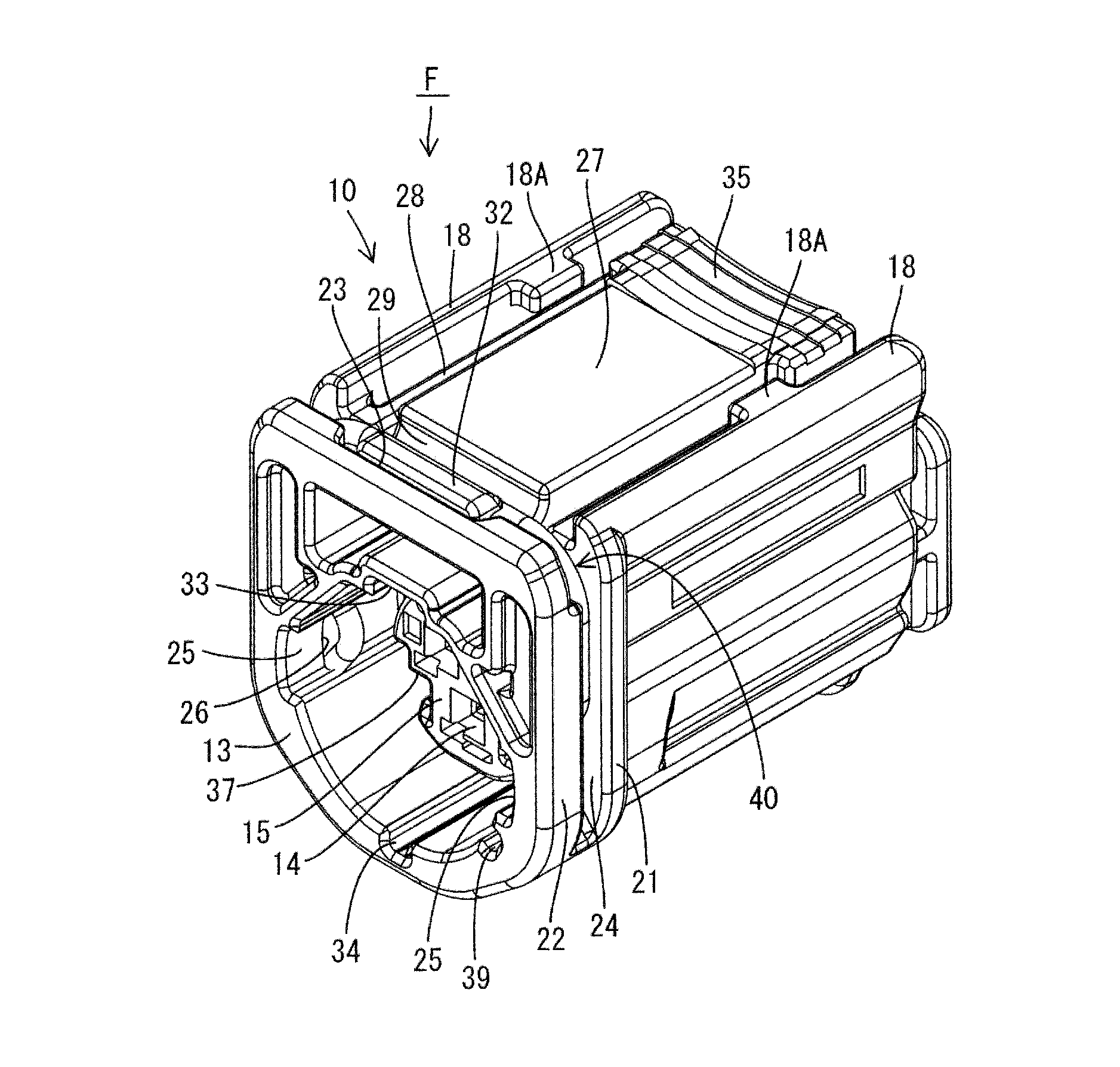
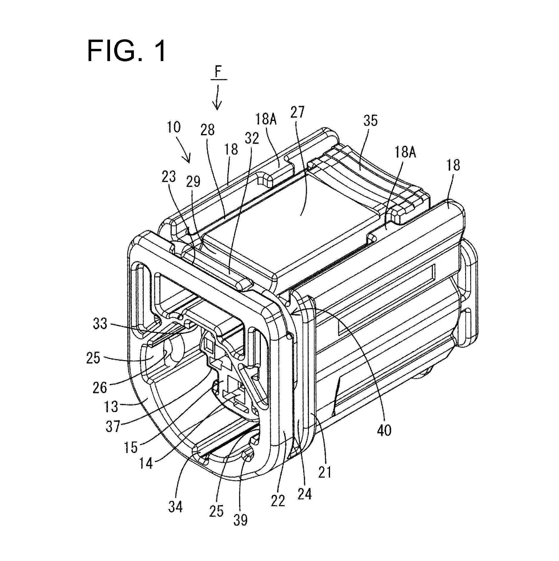
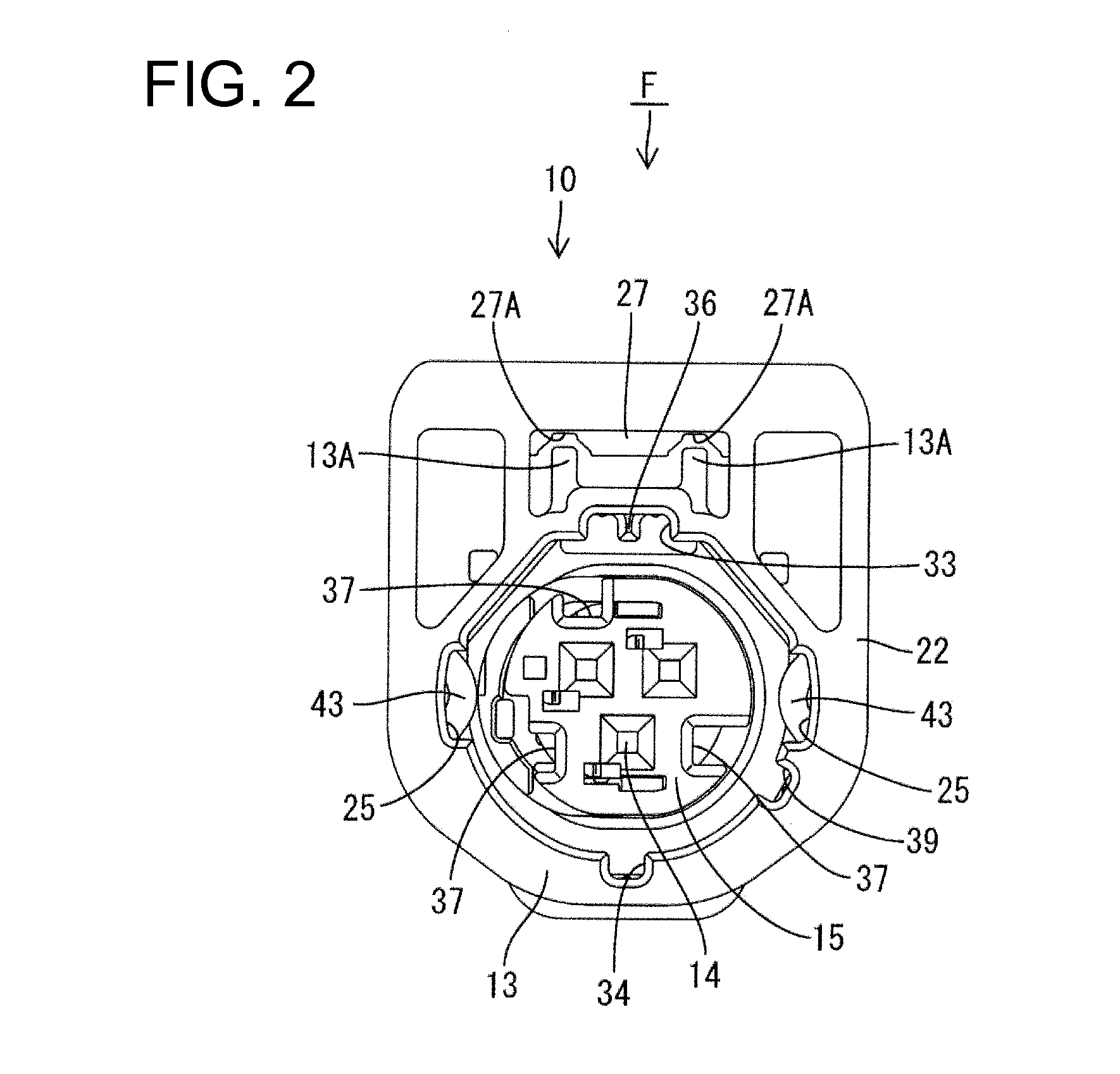
[0041]A spring lock connector in accordance with this embodiment has a female connector F shown in FIG. 1 and a male connector M shown in FIG. 19. The female connector F has a female housing 10 that can be connected to a male housing 50 of the male connector M. A spring 40 is mounted on the female housing 10 and locks the connectors F, M in a properly connected state. In the following description, forward and backward directions are based on a connecting direction of the two connectors F, M and connecting ends thereof are referred to as front ends. Further, vertical and lateral directions are based on FIGS. 2 and 20.

[0042]The male housing 50 made of synthetic resin and, as shown in FIG. 19, a hexagon nut N is held on a rear end of the male housing 50. As shown in FIG. 20, the male housing 50 has a substantially circular outer shape and is substantially coaxial with the hexagon nut N. Further, the male housing 50 does not bulge out from the outer shape of the hexagon nut N so that th...


PUM


Abstract

A spring lock connector includes a female connector (F) with a lock arm (27) capable of releasing locking by lifting up the spring. Left and right protection walls (18) are arranged at opposite left and right sides of the lock arm (27). Left and right resilient pieces (28) extend in forward and backward directions between the lock arm (27) and the protection walls (18) for coupling the lock arm (27) to the protection walls (18). Left and right displacement preventing walls (20) are provided at an interval narrower than the protection walls 18 below the protection walls (18). A rear part of the lock arm (27) is fit into a clearance between the both displacement preventing walls (20) together with the resilient pieces (28) when the lock arm (27) is unlocked, thereby preventing lateral displacements of the lock arm (27).

Description

BACKGROUND[0001]1. Field of the Invention[0002]The invention relates to a spring lock connector in which a spring locks male and female connectors in a properly connected state.[0003]2. Description of the Related Art[0004]U.S. Pat. No. 7,588,454 discloses a spring lock connector that has a male connector with a receptacle, a female connector with a terminal accommodating portion to be fit in the receptacle and a spring to lock the male and female connectors in a properly connected state. The female connector further has an outer tube surrounding an outer periphery of the terminal accommodating portion. The spring has a U-shape with left and right legs and an upper part that couples the left and right legs. The spring is fit on the outer tube so that the left and right legs sandwich the outer tube from left and right sides. A lock arm is provided on the upper surface of the outer tube for releasing locking by lifting up an upper side of the spring.[0005]Protection walls are arranged ...

Claims


Application Information

Patent Timeline
Patent Type & Authority Applications(United States)
IPC IPC(8): H01R13/627H01R13/64
CPCH01R13/64H01R13/627H01R13/6272H01R13/639
Inventor HIRAMATSU, HIROYUKI
Owner SUMITOMO WIRING SYST LTD
Why Eureka
Try Eureka