Laser machine, laser machining method, planar-member machining system, and planar-member machining method

a laser machining method and laser machining technology, applied in the direction of metal-working feeding devices, soldering devices, auxilary welding devices, etc., can solve the problem of difficult to efficiently transfer the workpiece, achieve the effect of reducing the height at which the workpiece is placed, easy and efficient transfer, and lowering the workpiece rack

Active Publication Date: 2018-07-12
MURATA MASCH LTD
View PDF7 Cites 4 Cited by
  • Summary
  • Abstract
  • Description
  • Claims
  • Application Information

AI Technical Summary

Benefits of technology

[0010]According to preferred embodiments of the present invention, a workpiece is able to be transferred to the other workpiece support or the like easily and efficiently by raising and lowering the workpiece rack. Even if the upper end of the workpiece rack is melted and thus the height at which the workpiece is placed is reduced, the workpiece is able to be easily transferred to the other workpiece support by raising and lowering the workpiece rack. Also, the distance between the laser head and the workpiece is able to be easily adjusted by adjusting the position to which the workpiece rack is raised.
[0011]If the machining region is set in the position at which the workpiece rack is raised by the elevator, the machined workpiece is able to be transferred from the workpiece rack easily and reliably by lowering the workpiece rack after laser machining. If the workpiece rack is able to travel relative to the body frame and the elevator includes a rod that is disposed on one of the workpiece rack and the body frame and driven vertically and a receiver that is disposed on the other of the workpiece rack and the body frame and receives a front end of the rod, the workpiece rack is able to be easily raised and lowered using the simple configuration including the vertically driven rod and the receiver. If the front end of the rod is in the shape of a cone, a truncated cone, or a sphere and the receiver has a conical, truncated conical, or spherical recess into which the front end of the rod is inserted, the workpiece rack is able to be easily positioned relative to the body frame by inserting the front end of the rod into the recess. If the elevator includes multiple elevators that support multiple portions of the workpiece rack and raise and lower the workpiece rack, the workpiece rack is able to be raised and lowered in a well-balanced manner by the elevators. If the receiver or the rod on the workpiece rack is adjustable horizontally so as to correspond to the rod or the receiver on the body frame, the rod and the receiver are able to be aligned with each other. Even if multiple workpiece racks are used alternately, each workpiece rack is able to be adapted to the elevator.
[0012]According to planar-member machining systems and planar-member machining methods of various preferred embodiments of the present invention, a workpiece is able to be transferred to the other workpiece support or the like easily and efficiently by raising and lowering the workpiece rack. Even if the upper end of the workpiece rack is melted and thus the height at which the workpiece is placed is reduced, the workpiece is able to be easily transferred to the other workpiece support by raising and lowering the workpiece rack. Also, the distance between the laser head and the workpiece is able to be easily adjusted by adjusting the position to which the workpiece rack is raised. Also, the workpiece W is easily transferred to the workpiece support and thus the workpiece W is able to be easily formed by the second machine.
[0013]According to laser machining methods of various preferred embodiments of the present invention, a workpiece is able to be transferred to the workpiece support easily and efficiently by lowering the workpiece rack. Also, the position in which the workpiece is laser-machined is able to be easily adjusted by adjusting the position to which the workpiece rack is raised. Also, if the laser machining method includes positioning the workpiece rack horizontally relative to the body frame in raising the workpiece rack, the raised workpiece rack is able to be reliably positioned relative to the frame body.

Problems solved by technology

Also, preventing the workpiece from interfering with the laser head requires previously retracting the laser head, making it difficult to transfer the workpiece efficiently.

Method used


Image

  • Laser machine, laser machining method, planar-member machining system, and planar-member machining method
  • Laser machine, laser machining method, planar-member machining system, and planar-member machining method
  • Laser machine, laser machining method, planar-member machining system, and planar-member machining method

Examples


Embodiment Construction

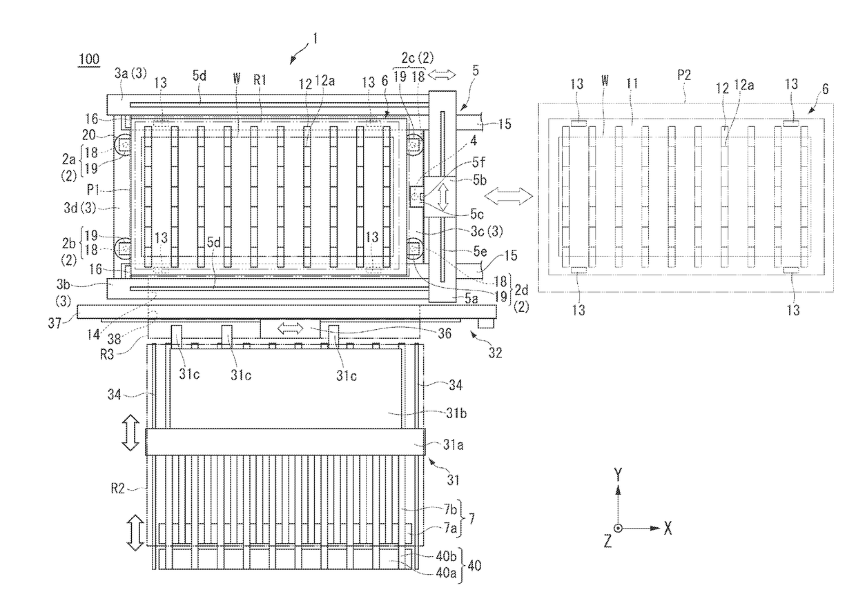
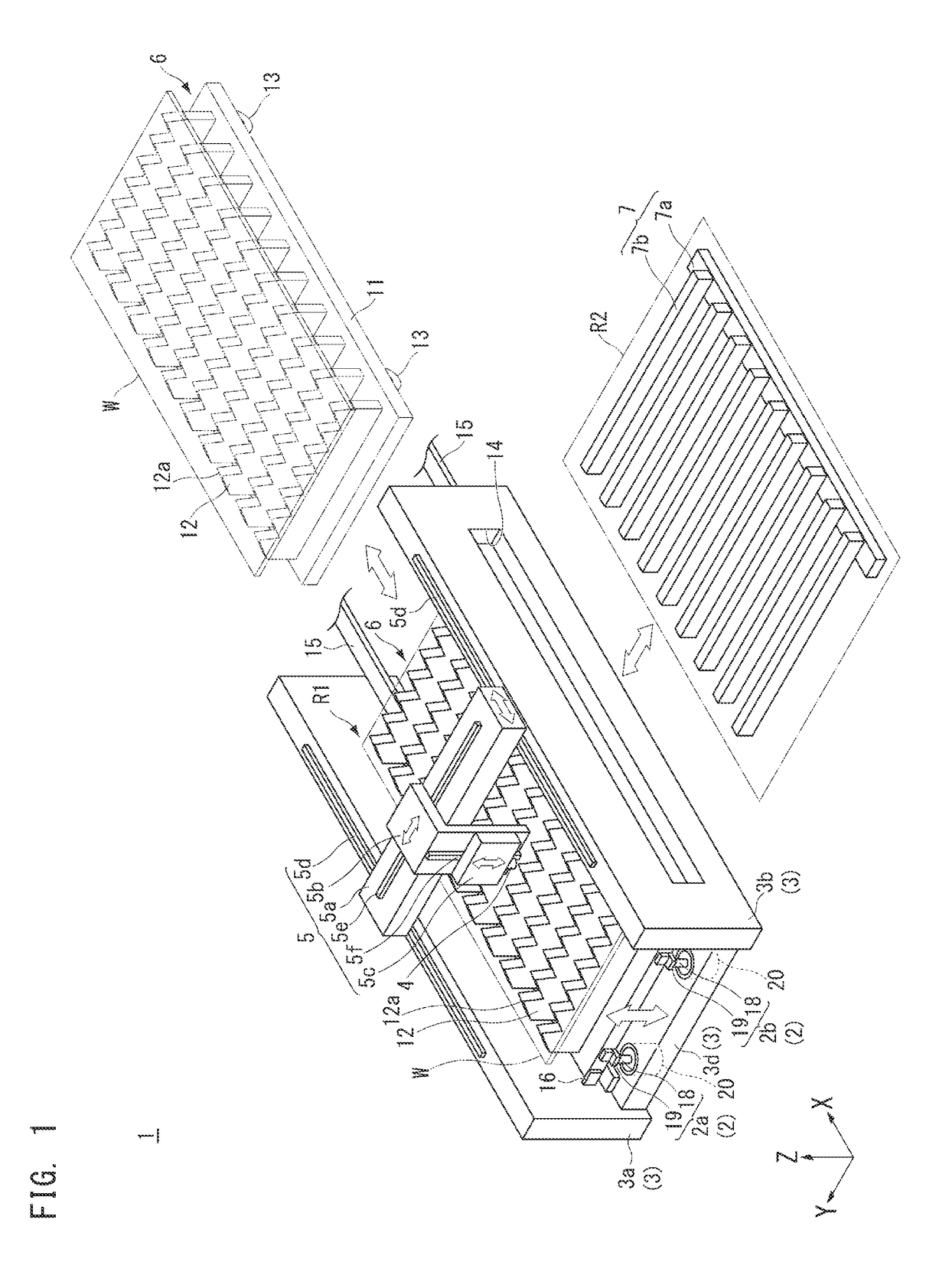
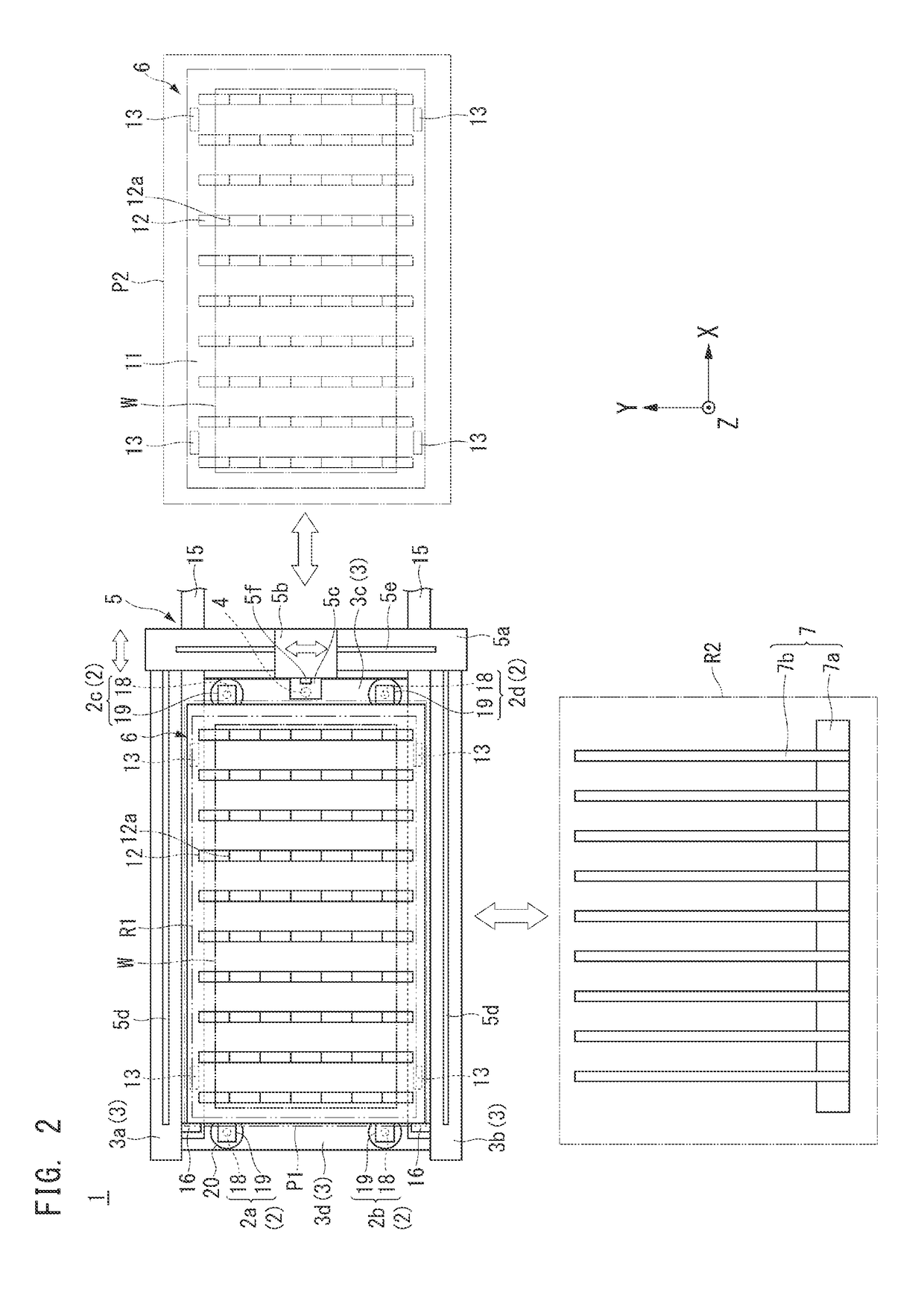
[0027]Now, preferred embodiments of the present invention will be described with reference to the drawings. However, the present invention is not limited thereto. To clarify the preferred embodiment, the drawings are scaled, for example, partially enlarged or highlighted, as necessary. In the drawings, directions are shown by an XYZ coordinate system. In this XYZ coordinate system, a plane parallel with the horizontal plane is defined as an XY-plane. Any direction parallel with the XY-plane is defined as an X-direction, and a direction perpendicular to the X-direction is defined as a Y-direction. The direction perpendicular to the XY-plane is defined as the vertical direction or a Z-direction. In the present specification, the upward direction is the positive Z-direction, and the downward direction is the negative Z-direction. In the drawings, the directions of arrows represent the positive X-, Y-, and Z-directions, and the directions opposite to the directions of the arrows represe...


PUM

PropertyMeasurementUnit
shapeaaaaaaaaaa
heightaaaaaaaaaa
distanceaaaaaaaaaa

Abstract

A laser machine includes a laser head that machines a planar workpiece in a machining region while moving relative to the workpiece, a workpiece rack that is able to travel with the workpiece placed thereon, and an elevator that is able to locate the workpiece in the machining region by raising and lowering the workpiece rack with the workpiece placed thereon.

Description

BACKGROUND OF THE INVENTION1. Field of the Invention[0001]The present invention relates to a laser machine, a laser machining method, a planar-member machining system, and a planar-member machining method.2. Description of the Related Art[0002]Examples of known apparatuses that cut a workpiece include laser machines (for example, see Japanese Unexamined Patent Application Publication No. 5-23877). A laser machine cuts a workpiece placed on a workpiece rack by moving a laser head relative to the workpiece while applying a laser to the workpiece.[0003]The workpiece machined by the laser machine is transferred from the workpiece rack to another workpiece support or the like and carried to a predetermined place. This transfer of the workpiece from the workpiece rack to the other workpiece support is required to be performed stably and efficiently. For example, transfer of the workpiece placed on the workpiece rack by lifting it using the other workpiece support requires a space through ...

Claims


Application Information

Patent Timeline
Patent Type & Authority Applications(United States)
IPC IPC(8): B23K26/38B23K37/04
CPCB23K26/38B23K37/0408B21D43/10B23P23/00B23K26/10B30B13/00
Inventor OZEKI, KOJI
Owner MURATA MASCH LTD
Why Eureka
Try Eureka