
Exhaust-steam casing for a steam turbine and assembly system
- Summary
- Abstract
- Description
- Claims
- Application Information
AI Technical Summary
Benefits of technology
Problems solved by technology
Method used
Image

Examples
first embodiment
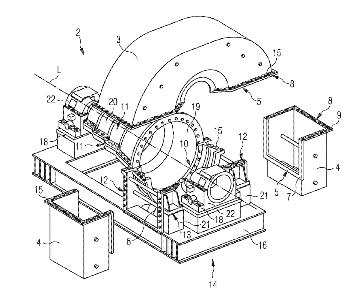
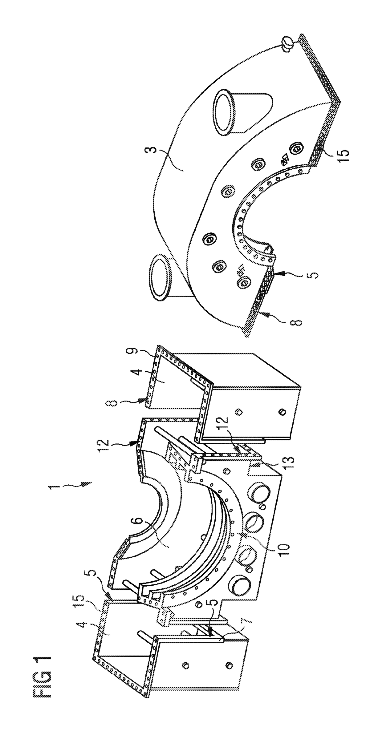
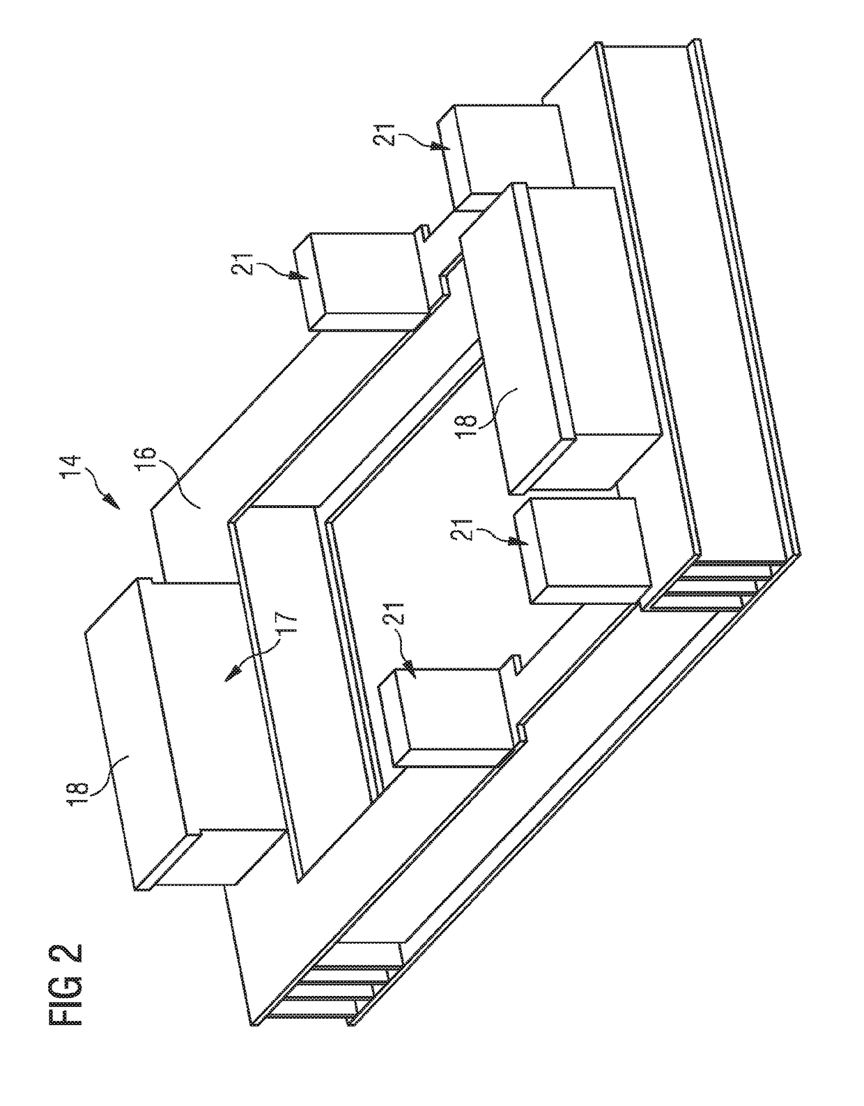
[0044]FIG. 3 shows an assembly system according to the invention for a turbine 2. A rotor shaft with moving blades and stationary blades is not depicted. In this view, two rotor shaft bearings 22 are arranged on rotor shaft bearing mountings 18 of the turbine framework 14. A longitudinal axis L of the rotor shaft runs through the rotor shaft bearings 22. Arranged between the rotor shaft bearings 22 is a turbine casing 11 with a lower turbine casing part 19 and an upper turbine casing part 20. On an end face of the lower turbine casing part 19, a lower exhaust-steam casing part 6 is arranged and detachably fixed on it by means of fastening bolts that are not shown. In a non-assembled state, the exhaust-steam casing 1 shown in FIG. 1, with the upper exhaust-steam casing part 3 and two side exhaust-steam casing parts 4, is arranged around the turbine framework 14. The assembly system shown can consequently be transported for example in two units, a first unit comprising the turbine fra...
second embodiment
[0045]The turbine framework 14 shown in FIG. 4 is designed for assembling an exhaust-steam casing according to the invention that is shown in FIG. 5. The turbine framework 14 has a turbine frame 16 with a rectangular base area, rotor shaft bearing mountings 18 being arranged on short sides. Between the rotor shaft bearing mountings 18, the turbine framework 14 has a turbine casing mounting 14. Arranged on the turbine frame 16 alongside a rotor shaft mounting 18 are metal sheets 24, on which upper exhaust-steam casing part connection surfaces 8, turbine casing connection surfaces 10 and exhaust-steam casing connection surfaces 12 are formed. The metal sheets 24 are arranged on the turbine framework 14 in such a way that together with the turbine frame 16 they are a substitute for a lower exhaust-steam casing part 6.
[0046]The second embodiment of an assembly system according to the invention, shown in FIG. 5, has the turbine framework 14 from FIG. 4, a rotor shaft bearing 22 being arr...
PUM
 Abstract
Description
Claims
Application Information