Integrated liquid cooling device and method thereof

a liquid cooling device and integrated technology, applied in indirect heat exchangers, lighting and heating devices, instruments, etc., can solve the problems of affecting the emitted much heat, and seriously affecting the application and service life of products, so as to save external pipelines and space, reduce manufacturing accuracy and installation requirements, and simple structure

Inactive Publication Date: 2018-07-12
BLACKBEZT LIGHTING TECH CO LTD
View PDF14 Cites 6 Cited by
  • Summary
  • Abstract
  • Description
  • Claims
  • Application Information

AI Technical Summary

Benefits of technology

[0015]1. Said integrated liquid cooling device of the invention uses a structure that the first liquid reservoir, the second liquid reservoir, the first liquid channel, the second liquid channel, the third liquid channel and the liquid transfer cycle driver are arranged in the housing; all parts are internally installed as an integral encapsulation with a simple structure, saving external pipeline and space. The device has low requirements for manufacturing accuracy and installation, improving the safety; with small size, it can be widely used for cooling of heating components of the core parts in all kinds of electronic products, thus ensuring the safety of the electronic products. When all parts are internally installed as an integral encapsulation with less pipeline connecters, the risk of leakage is reduced and the reliability of cooling is increased.
[0016]2. The invention provides a new type of integrated liquid cooling device and a method thereof. With a compact structure, the cooling device has low requirements for manufacturing accuracy and installation and has easy and safety operation. The integrated liquid cooling device may use all sorts of metal that is conducive to heat dissipation as the housing. Using flat liquid channel may increase the contact effectiveness between the cooling liquid and the cooling fin, thus greatly improve the overall effect of heat dissipation. The cooling liquid in a fully sealed space flows unidirectionally in cycle through the liquid transfer cycle driver and the heat is driven to cycle by liquid in channels. The product is fully sealed, therefore, no liquid is to be added in the future and no liquid leakage will be worried about.

Problems solved by technology

The core parts of these products will emit much heat during operation, while the poor effect of heat dissipation may seriously affect the application and service life of the products.
The increased temperature of the products during operation may seriously affect their service life and waste the energy.
The core parts of all kinds of electronic equipment will emit much heat during operation, and the performance of the equipment will be seriously affected by the heat failed to be dissipated.
Some amateurs use water to cool the computers with DIY device, but the problems as leakage of water pipeline and connectors and aging of plastic pipelines in high-temperature water may occur.
In addition, such cooling method needs water tank, pump and fan arranged separately and taking up a lot of space, therefore, it cannot be industrialized on a large scale.

Method used


Image

  • Integrated liquid cooling device and method thereof
  • Integrated liquid cooling device and method thereof
  • Integrated liquid cooling device and method thereof

Examples


embodiment 1

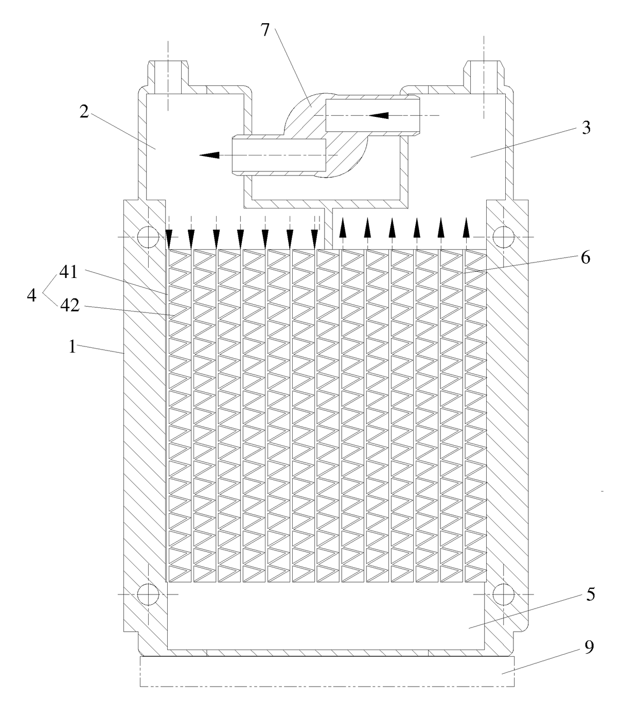
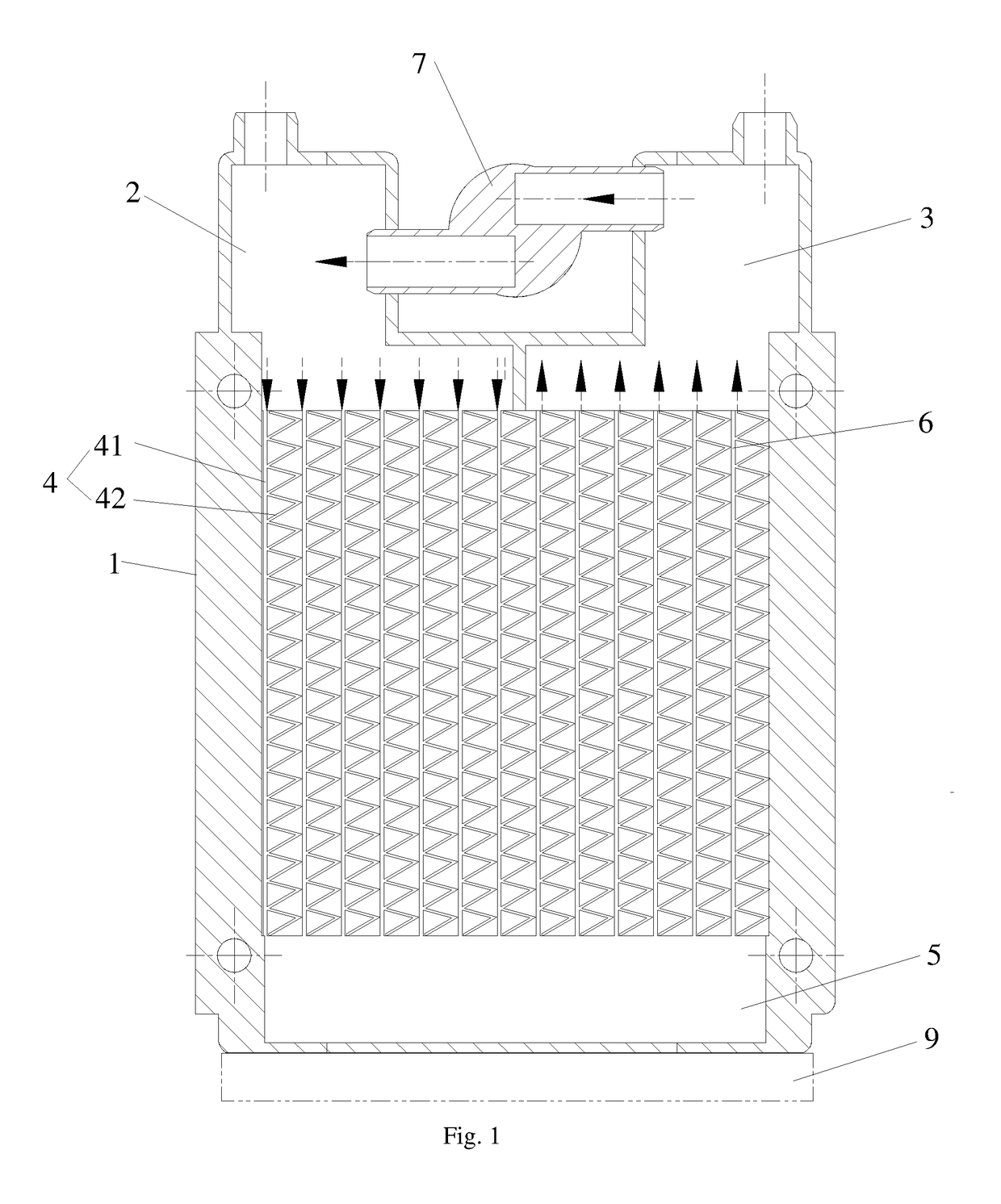
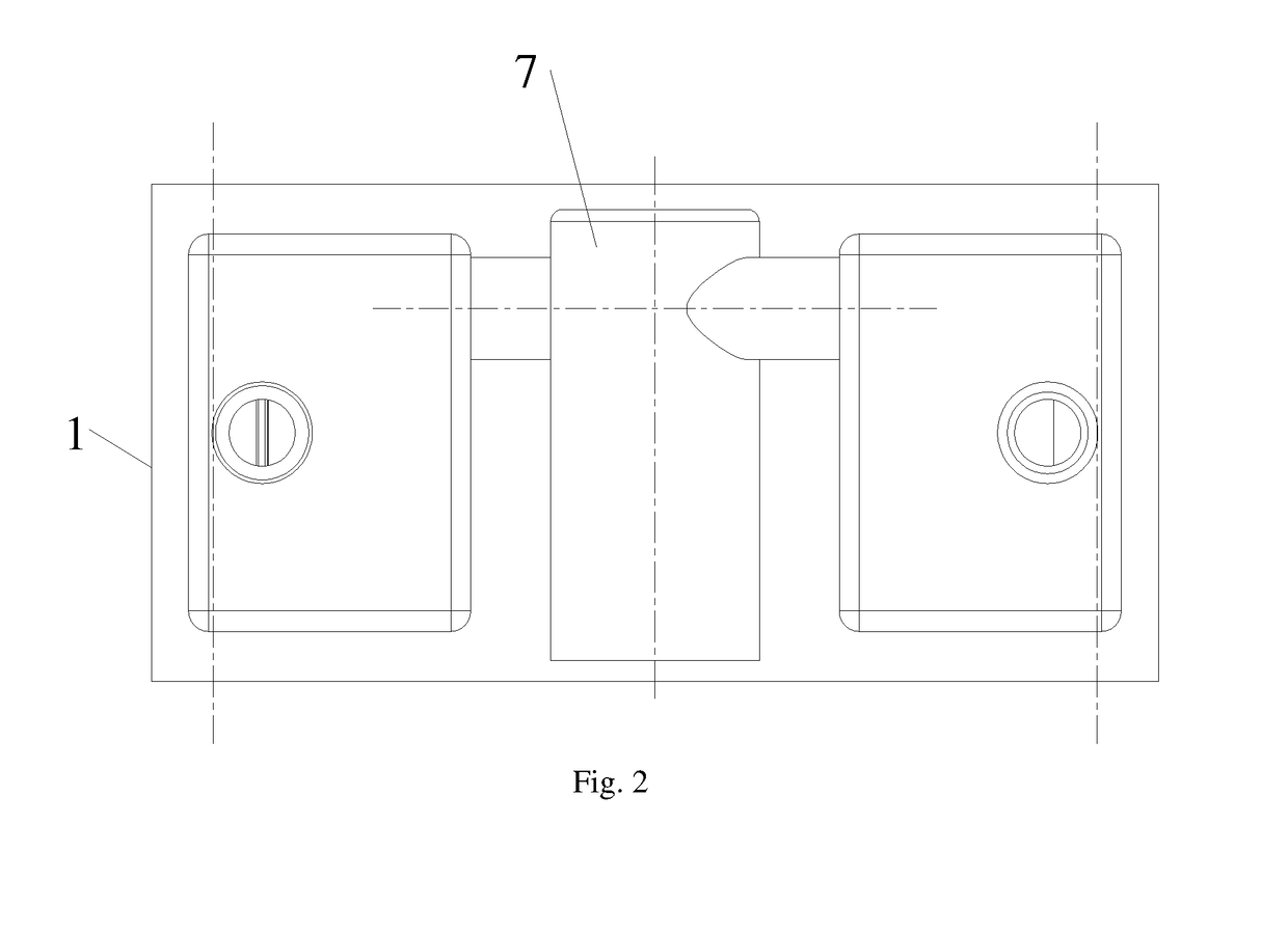
[0023]The integrated liquid cooling device of Embodiment 1 as shown in FIGS. 1-3, comprises a housing 1, a first liquid reservoir 2, a second liquid reservoir 3, at least one first liquid channel 4 for heat dissipation, a second liquid channel 5 appressed to heat source device 9, at least one third liquid channel 6 for heat dissipation and a liquid transfer cycle driver 7; the first liquid reservoir 2, the second liquid reservoir 3, the first liquid channel 4, the second liquid channel 5, the third liquid channel 6 and the liquid transfer cycle driver 7 are arranged in the housing 1. The first liquid reservoir 2 is connected to the second liquid channel 5 through the first liquid channel 4; the second liquid channel 5 is connected to the second liquid reservoir 3 through the third liquid channel 6; the first liquid reservoir 2 and the second liquid reservoir 3 are independent to each other and connected through the liquid transfer cycle driver 7; the liquid transfer cycle driver 7 t...

embodiment 2

[0026]The method of liquid cooling by using Embodiment 1 comprises: the first liquid reservoir 2, the first liquid channel 4, the second liquid channel 5, the third liquid channel 6 and the second liquid reservoir 3 form a complete flowing path in the housing 1; the liquid transfer cycle driver 7 drives the liquid to enter the first liquid reservoir 2 through the second liquid reservoir 3; the liquid flows circularly in the housing 1 through such driving; during this process, heat transfer will happen between the liquid in the second liquid channel 5 and the heat source device 9; the liquid takes away the heat of heat source device 9 and distribute the heat energy to the surfaces of the cooling fin in the first liquid channel 4 and the cooling fin in the third liquid channel 6 while flowing through the first liquid channel 4 and the third liquid channel 6 so as to realize heat dissipation; meanwhile, the fan rotates to accelerate the air flow so that the heat energy on the surfaces ...


PUM

PropertyMeasurementUnit
liquidaaaaaaaaaa
structureaaaaaaaaaa
heataaaaaaaaaa

Abstract

An integrated liquid cooling device comprises a housing, a first liquid reservoir, a second liquid reservoir, at least one first liquid channel for heat dissipation, a second liquid channel appressed to a heat source device, at least one third liquid channel for heat dissipation and a liquid transfer cycle driver; the first liquid reservoir is connected to the second liquid channel through the first liquid channel; the second liquid channel is connected to the second liquid reservoir through the third liquid channel; the first liquid reservoir and the second liquid reservoir are independent to each other and connected through the liquid transfer cycle driver; the liquid transfer cycle driver transfers the liquid in the second liquid reservoir to the first liquid reservoir. The invention saves the space and reducing the risk of leakage.

Description

CROSS REFERENCE TO RELATED APPLICATIONS[0001]The present application claims the benefit of Chinese Patent Application No. 201710012181.3 filed on Jan. 9, 2017, the contents of which are hereby incorporated by reference.TECHNICAL FIELD[0002]The Invention relates to the technical field of heat energy transfer device, and particularly to an integrated liquid cooling device and a method thereof.BACKGROUND ART[0003]In prior art, the CPU (Central Processing Unit) of desk computers, servers and laptops is cooled with fan at present. The core parts of these products will emit much heat during operation, while the poor effect of heat dissipation may seriously affect the application and service life of the products. All sorts of lamps will also emit much heat during illumination. The increased temperature of the products during operation may seriously affect their service life and waste the energy. The core parts of all kinds of electronic equipment will emit much heat during operation, and t...

Claims


Application Information

Patent Timeline
Patent Type & Authority Applications(United States)
IPC IPC(8): F28D1/02F28D15/00F28F23/02C09K5/10
CPCF28D1/024C09K5/10F28F23/02F28D15/00H05K7/20272F28F2250/08F28D1/05375G06F1/20H01L23/473G06F2200/201
Inventor MAI, JIANWEN
Owner BLACKBEZT LIGHTING TECH CO LTD
Why Eureka
Try Eureka