Uav-mounted dispersant device with electronic triggering mechanism

a dispersant device and electronic triggering technology, applied in the field of remote control of dispersant devices, can solve the problems of electric ignition mechanism capable of igniting flammable devices, and none of the examples of prior art cited above incorporates an incendiary elemen

Active Publication Date: 2018-07-19
AERIAL ENFORCEMENT SOLUTIONS LLC
View PDF8 Cites 11 Cited by
  • Summary
  • Abstract
  • Description
  • Claims
  • Application Information

AI Technical Summary

Problems solved by technology

None of the examples of prior art cited above incorporates an electrical ignition mechanism that is capable of igniting a flammable device such as smoke canister, firing a percussion-primed dispersant canister, firing an electrically primed dispersant canister, or actuating a pressurized canister via a linear solenoid.
In addition, none of the examples of prior art cited above incorporates an incendiary element, such as an electric match, that provides for the release of dispersant from a pressurized canister by melting or burning away the shutoff valve of the canister.

Method used


Image

  • Uav-mounted dispersant device with electronic triggering mechanism
  • Uav-mounted dispersant device with electronic triggering mechanism
  • Uav-mounted dispersant device with electronic triggering mechanism

Examples


first embodiment

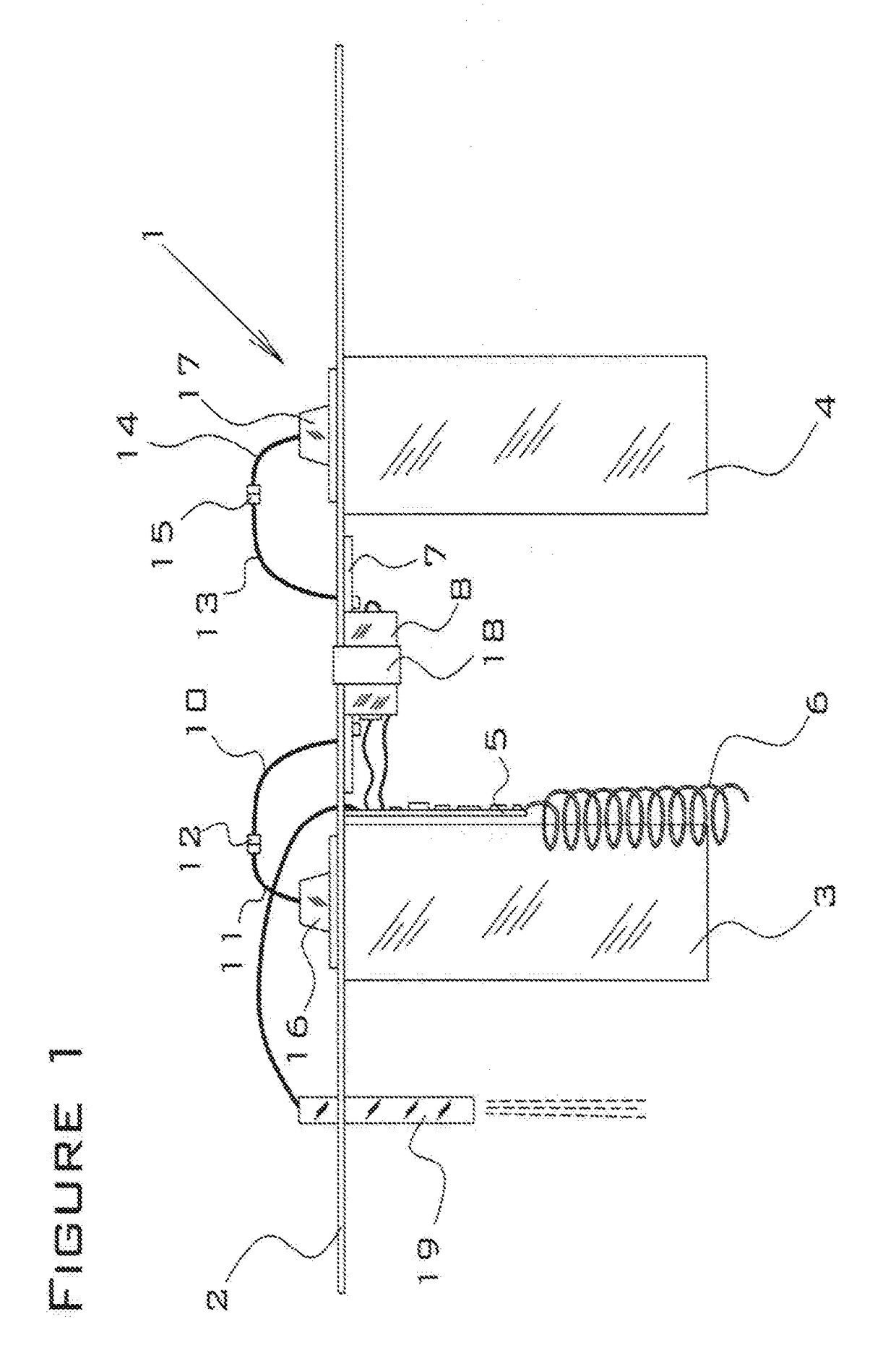
[0110]FIG. 7 is an exploded longitudinal cross-section view of the first smoke canister assembly 34 of the first embodiment, with the section line taken through the center of the first smoke canister 3. As shown, an electric match 35 is connected to the lower terminal end of the second wire pair 11. The second wire pair 11 passes through a central bore 36 of the first threaded top 16 and is connected at its upper terminal end to the first electrical connector 12. The male threaded portion 37 of the first threaded top 16 screws into the female threaded portion 38 of the first smoke canister 3. When the first smoke canister assembly 34 is assembled, the electric match 35 is positioned within the open central bore 39 of the first smoke canister 3. When the electric match 35 is ignited by passing an electric current through it, the flammable smoke-producing compound 40 within the first smoke canister 3 is ignited by flames produced by the burning electric match 35, and smoke is emitted ...

second embodiment

[0111]FIG. 8 is an exploded longitudinal cross-section view of the first percussion-primed chemical dispersant canister assembly 41 of the second embodiment, with the section line taken through the center of the first percussion-primed chemical dispersant canister 27. The first percussion-primed chemical dispersant canister 27 comprises a percussion primer 42 that is similar to the primers comprised in common firearm ammunition (such as the primers in 12-gauge shotshells), a propellant charge 43, a chemical dispersant agent 44, a casing 45, a first wad 46 that separates the propellant charge 43 from the chemical dispersant agent 44, and a second wad 47 that secures the chemical dispersant agent 44 within the casing 45. The first linear solenoid 25 is mounted to the first solenoid connector 28. The first solenoid connector 28 is removably attachable to the first percussion-primed chemical dispersant canister 27 by screwing the male threaded portion 48 of the first solenoid connector ...


PUM


Abstract

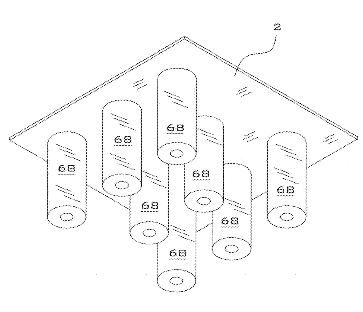
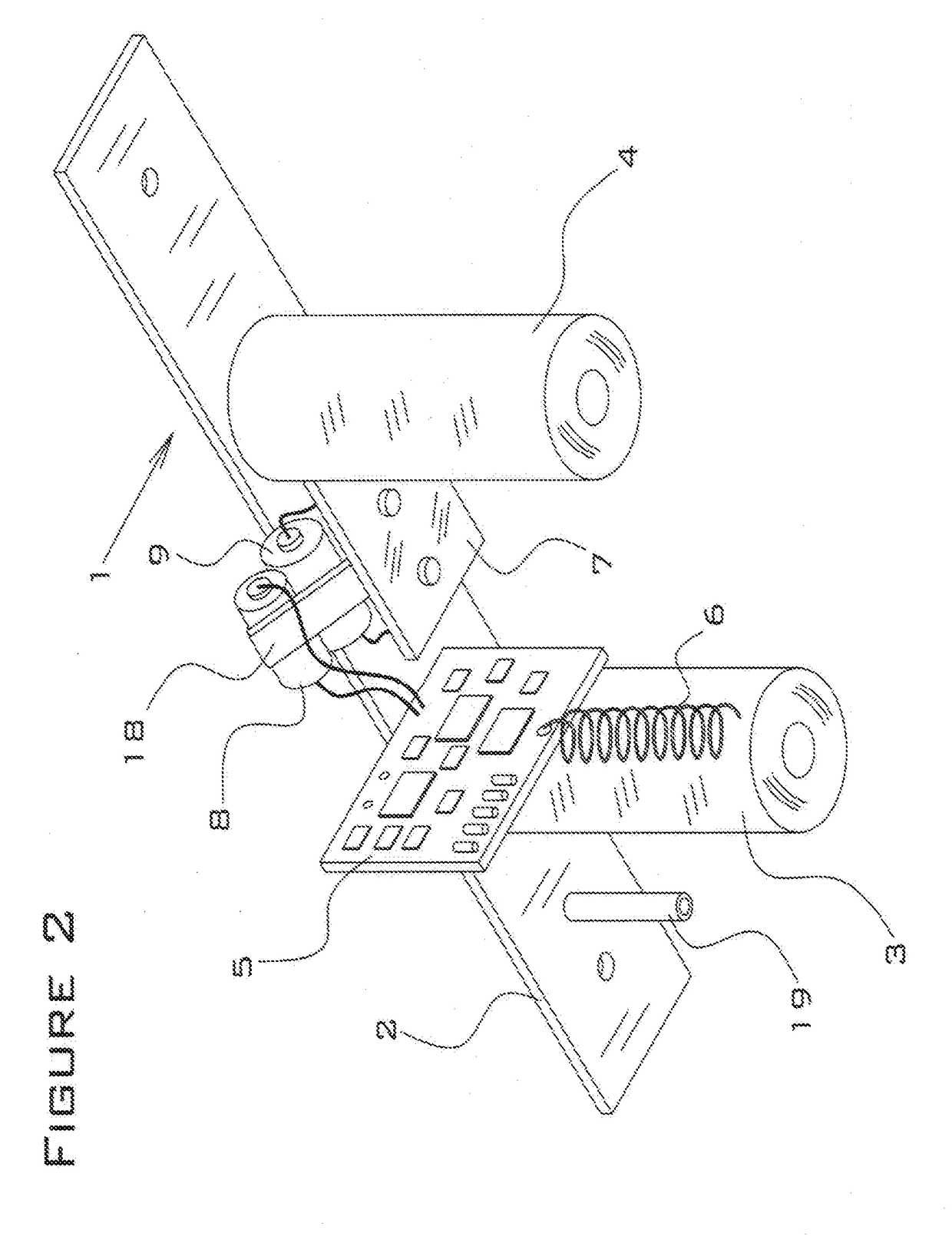
An accessory for an unmanned aerial vehicle (UAV) comprising a baseplate that is attached to the UAV unmanned aerial vehicle, at least one dispersant canister that is removably attached to the baseplate, a radio frequency receiver, an auxiliary circuit board, at least one battery, first and second wire pairs that supply electrical current from the auxiliary circuit board, a protective housing, and a radio frequency transmitter that is in communication with the radio frequency receiver. In alternate embodiments, the invention further comprises an electric match, linear solenoid, or electric primer.

Description

BACKGROUND OF THE INVENTION[0001]The present invention relates to the field of devices that deliver and disperse airborne chemical agents, and more particularly, to remotely controlled dispersal devices that comprise electrical ignition systems to initiate the dispersal of chemicals.1. Description of the Related Art[0002]There are numerous examples of unmanned aerial vehicles (UAVs) that are designed for specific purposes and the subject of issued patents and published patent applications, but none of these inventions incorporates the structural features and functional capabilities of the present invention. The present invention is a dispersant delivery device that is removably mountable on a variety of types and sizes of UAVs. The present invention utilizes remotely-controlled electrical currents to initiate the release of chemical agents such as colored smoke, chemical irritants and fire retardants. These dispersants may be used for a wide variety of applications including riot co...

Claims


Application Information

Patent Timeline
Patent Type & Authority Applications(United States)
IPC IPC(8): B64D1/16G05D1/00B64C39/02
CPCB64D1/16G05D1/0038F41H9/06A62C3/0235B64C39/024A62C3/0242B05B13/005B65D83/262F42B12/46
Inventor KRAMER, MICHAEL TODD
Owner AERIAL ENFORCEMENT SOLUTIONS LLC
Why Eureka
Try Eureka