Method for cleaning a machine for braiding electrical cables

Active Publication Date: 2018-07-19
SAFRAN ELECTRICAL & POWER
View PDF0 Cites 4 Cited by
  • Summary
  • Abstract
  • Description
  • Claims
  • Application Information

AI Technical Summary

Benefits of technology

[0007]The present invention provides a simple, effective

Problems solved by technology

This maintenance operation is time-consuming and cumbersome.
In this process, the user handling the s

Method used


Image

  • Method for cleaning a machine for braiding electrical cables
  • Method for cleaning a machine for braiding electrical cables
  • Method for cleaning a machine for braiding electrical cables

Examples


Embodiment Construction

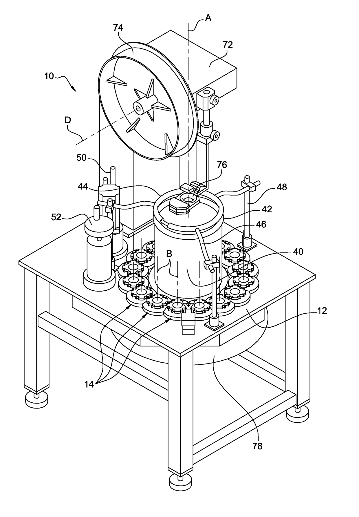
[0037]Although the braiding machine 10 from FIG. 1 has already been described above, it will be described in more detail below.

[0038]The machine 10 comprises a table of which the upper platform forms the above-mentioned platform 12. The platform 12 is substantially horizontal in the example shown. It has a central chamber 40 which has a vertical axis A and around which the row of members 14 extends.

[0039]The chamber 40 extends upwards from the platform 12 and has, on its upper end, a first ring 42 which has a rotational axis A.

[0040]A second ring 44 having the rotational axis A is arranged above the first ring 42 and at a distance therefrom so as to allow wires to pass between the rings 42, 44. The second ring 44 is connected to the upper ends of vertical rods 48 by means of substantially horizontal bars 46, the lower ends of which rods are attached to the platform 12. The rods 48, in this case three rods, are uniformly distributed around the axis A.

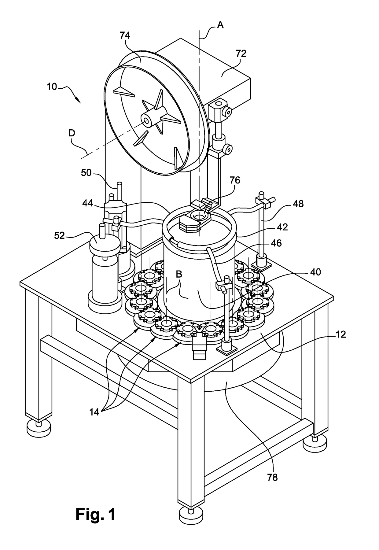
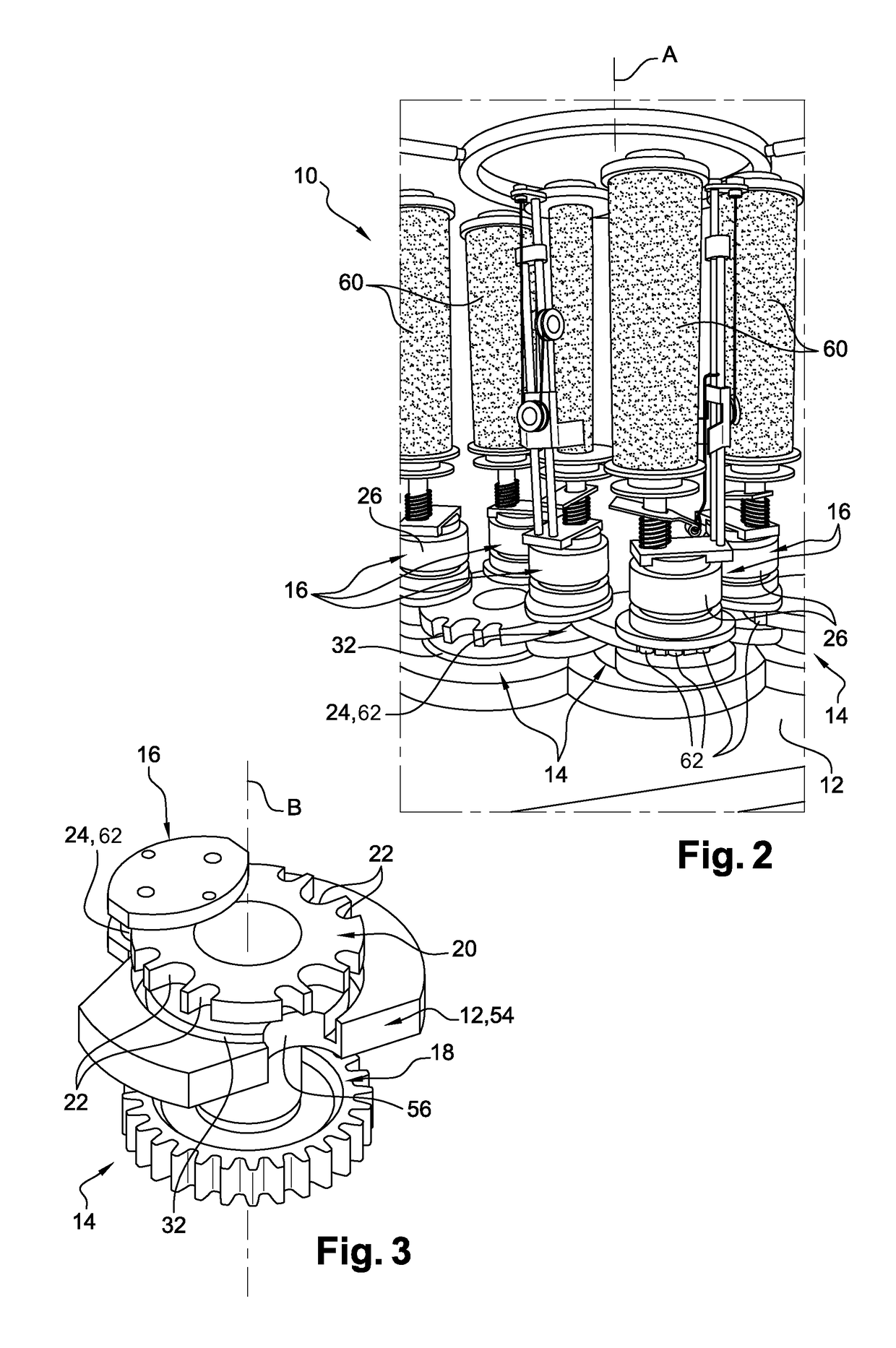
[0041]The wheel 22 of each member...


PUM


Abstract

Method for cleaning a braiding machine, particularly a machine for braiding electrical cables, said braiding machine comprising a plateau (12) for supporting an annular row of spindle drive members (14), characterized in that it comprises a step of equipping the machine with at least one cleaning tool (14), this cleaning tool comprising on the one hand means (90) configured to be driven by the members and, on the other hand, at least one guide element configured to be housed in slideways (32) for the movement of the tool, said guide element being configured to drive or to be equipped with a means (80) of cleaning said slideways, and a step of rotating said members so as to drive said cleaning means in said slideways.

Description

TECHNICAL FIELD[0001]The present invention relates to a method for cleaning a braiding or overbraiding machine, in particular for electrical cables. The braid or overbraid forms a shield for the cable, for example.PRIOR ART[0002]A braiding machine, as shown in FIGS. 1 and 2 and provided with reference numeral 10, comprises a platform12 for supporting an annular row of members 14 for driving bobbins 16. The members 14 extend around a first common axis A and are rotatably movable about second axes B which are substantially parallel to one another and to the first axis A.[0003]The members 14, which can be seen more clearly in FIG. 3, each comprise a pinion 18, which is meshed with pinions 18 of adjacent members and a wheel 20, which comprises notches 22 over its circumference that are designed to receive complementary means 24 of the bobbins 16 so as to drive said bobbins about the second axes B.[0004]As can be seen in FIGS. 6 and 7, each bobbin 16 has a lower base 26 and an upper coil...

Claims


Application Information

Patent Timeline
IPC IPC(8): D04C3/48D04C3/40B08B1/00B08B1/04B08B13/00
CPCD04C3/48D04C3/40B08B1/006B08B1/04B08B13/00D10B2401/16H01B13/2606
Inventor BOFF, ANA L
Owner SAFRAN ELECTRICAL & POWER
Why Eureka
Try Eureka