Resonator and resonance device

Active Publication Date: 2018-07-19
MURATA MFG CO LTD
View PDF4 Cites 1 Cited by
  • Summary
  • Abstract
  • Description
  • Claims
  • Application Information

AI Technical Summary

Benefits of technology

The patent aims to prevent the appearance of a false mode in a resonator that causes bending. The technical effect of this patent is to improve the performance and reliability of the resonator.

Problems solved by technology

However, in the existing resonance device disclosed in Patent Document 1, for example, an unwanted vibration mode (spurious mode) occurs at frequencies around a main vibration mode at a desired frequency.

Method used


Image

  • Resonator and resonance device
  • Resonator and resonance device
  • Resonator and resonance device

Examples


first embodiment

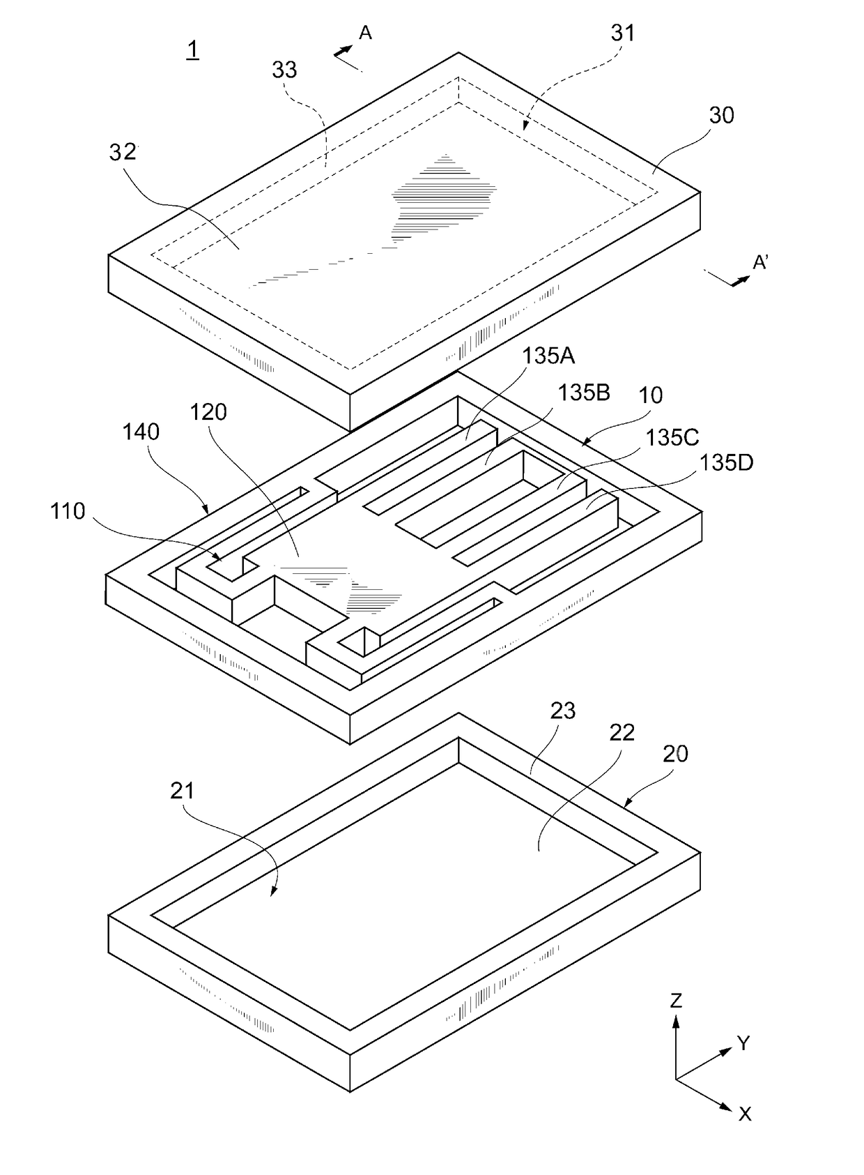
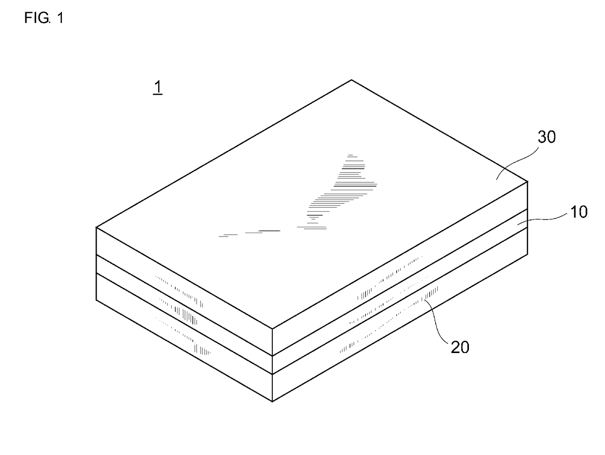
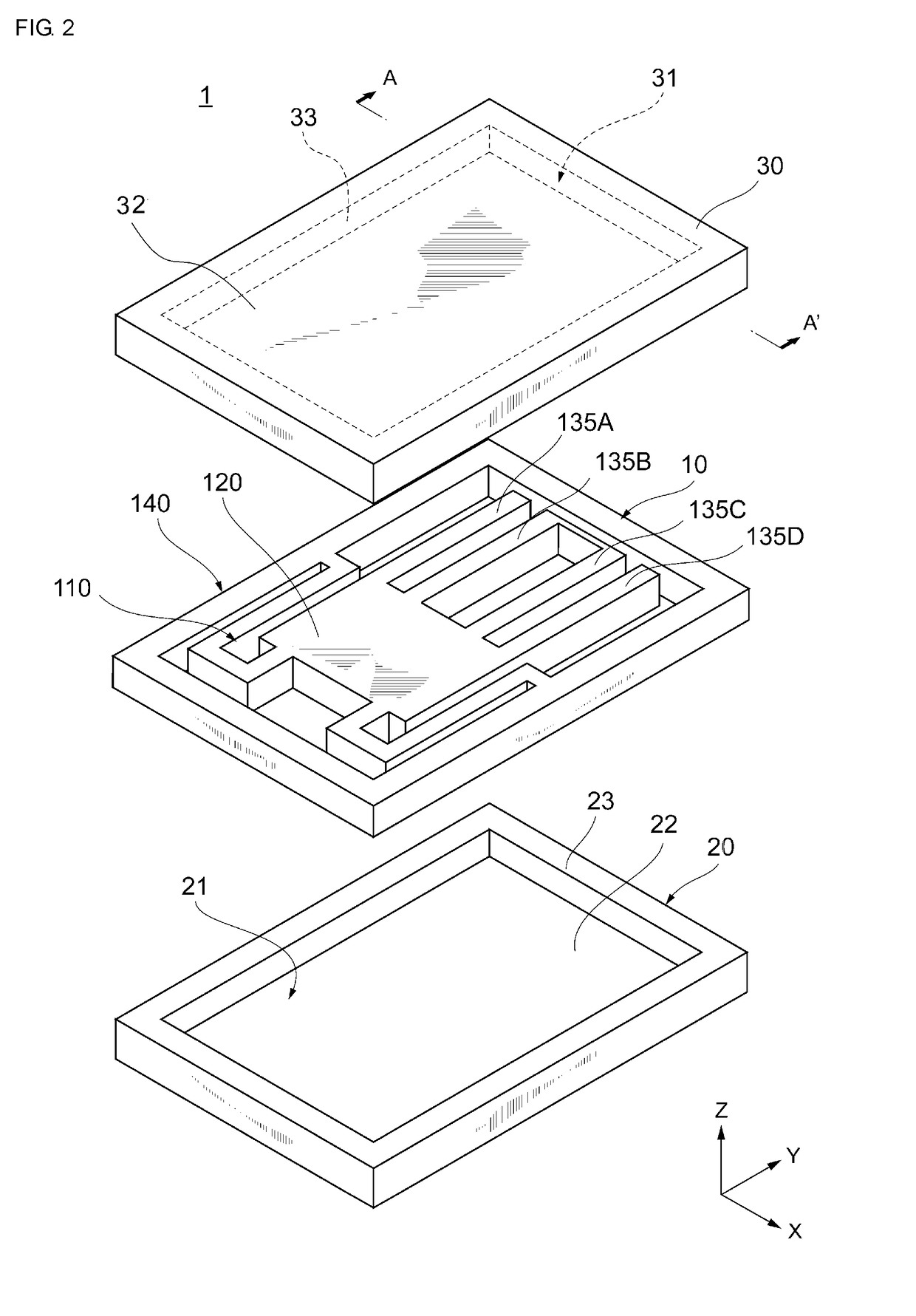
[0016]Hereinafter, a first exemplary embodiment of the present disclosure will be described with reference to the accompanying drawings. FIG. 1 is a perspective view schematically showing the appearance of a resonance device 1 according to the first exemplary embodiment. FIG. 2 is an exploded perspective view schematically showing the structure of the resonance device 1 according to the first exemplary embodiment.

[0017]As shown, the resonance device 1 includes a resonator 10, and an upper cover 30 and a lower cover 20 provided with the resonator 10 interposed therebetween. That is, the resonance device 1 is formed by the lower cover 20, the resonator 10, and the upper cover 30 being laminated in this order.

[0018]The resonator 10, and the lower cover 20 and the upper cover 30 are joined, whereby the resonator 10 is sealed and a vibration space for the resonator 10 is formed. Each of the resonator 10, the lower cover 20, and the upper cover 30 is formed by using a Si substrate. The re...

second embodiment

[0068]In second and subsequent embodiments, the description of matters common to the first exemplary embodiment is omitted, and the differences will be described. In particular, the same advantageous effects achieved by the same configuration are not mentioned successively in each embodiment.

[0069]In particular, FIG. 6 is a diagram showing an example of a plan view of a resonator 10 according to the another exemplary embodiment. Hereinafter, of the detailed configuration of the resonance device 1 according to the present embodiment, the difference from the first embodiment will be mainly described.

[0070]In the present embodiment, the vibration portion 120 has a connection portion 139 in addition to the connection portion 138. The connection portion 139 connects the distal ends of the vibration arm 135A and the vibration arm 135D. The vibration arm 135 according to the present embodiment may be configured to have the connection portion 139 and not to have the connection portion 138.

[...


PUM


Abstract

A resonator including a base; two or more vibration arms connected at ends thereof to a front end of the base and spaced apart from each other across a predetermined space and extending away from the base. Moreover, a connection member connects the vibration arms that bend in the same direction when an electric field is applied. The resonator inhibit occurrence of a spurious mode that otherwise occurs in a resonator that performs out-of-plane bending.

Description

CROSS REFERENCE TO RELATED APPLICATIONS[0001]The present application is a continuation of PCT / JP2016 / 072553 filed Aug. 1, 2016, which claims priority to Japanese Patent Application No. 2015-248945, filed Dec. 21, 2015, the entire contents of each of which are incorporated herein by reference.TECHNICAL FIELD[0002]The present disclosure relates to a resonator and a resonance device in which a plurality of vibration arms vibrate in a bending vibration mode.BACKGROUND[0003]Currently, resonance devices using a MEMS (Micro Electro Mechanical Systems) technique are used as timing devices, for example. Such a resonance device is generally mounted on a printed circuit board that is incorporated into an electronic device such as a smartphone. The resonance device includes a lower substrate, an upper substrate that forms a cavity between the lower substrate and the upper substrate, and a resonator that is disposed within the cavity between the lower substrate and the upper substrate.[0004]For ...

Claims


Application Information

Patent Timeline
IPC IPC(8): H03H9/05H03H9/10H03H9/13H03H9/17
CPCH03H9/0595H03H9/10H03H9/13H03H9/17H03H2009/155H03H9/1057H03H9/2489
Inventor HIROTA, WAKANAUNAMI, TOSHIHIKOINOUE, YOSHIHISA
Owner MURATA MFG CO LTD
Why Eureka
Try Eureka