Oil mist separator

Active Publication Date: 2018-07-26
TOYOTA BOSHOKU KK
View PDF21 Cites 8 Cited by
  • Summary
  • Abstract
  • Description
  • Claims
  • Application Information

AI Technical Summary

Benefits of technology

[0054]According to the oil mist separator 1A of this Example, the chamber 15 which is partitioned from the gas flow passage 4 including the gas introduction port 11 is provided between the cylinder head cover 2 and the baffle plate 3; the first guide wall 21 which extends with a downward inclination toward the chamber 15 so as to cover the gas introduction port 11 and the chamber 15 is provided above the gas introduction port 11 and the chamber 15; and the drain hole 17 for discharging the oil within the chamber 15 is formed in the baffle plate 3. Thus, the scattered oil flowing from the gas introduction port 11 into the gas flow passage 4, in the scattered oil splashed by rotation of the cam shaft 6, collides with the first guide wall 21, and is transmitted along the first guide wall 21 and introduced into the chamber 15. Then, the oil within the chamber 15 is discharged through the drain hole 17 to the side of the cam chamber 10, at a position distant from directly below the gas introduction port 11. Accordingly, the oil discharged to the side of the cam chamber 10 is hard to be re-carried away due to collision with the scattered oil by rotation of the cam shaft 6 or the flow of blow-by gas having a high flow velocity, thereby making it possible to improve the oil separation efficiency. Further, it is unnecessary to provide a shielding plate on the outer side of the gas introduction port 11 as conventional, and excellent installation properties are obtained.
[0055]In this Example, the first guide wall 21 is composed of a part of the ceiling wall 2a of the cylinder head cover 2. Thus, a simple and small s

Problems solved by technology

Thus, the returned oil collides with the scattered oil splashed by rotation of the cam shaft, so that the scattered oil is easily re-c

Method used


Image

  • Oil mist separator
  • Oil mist separator
  • Oil mist separator

Examples


example 1

(1) Configuration of Oil Mist Separator

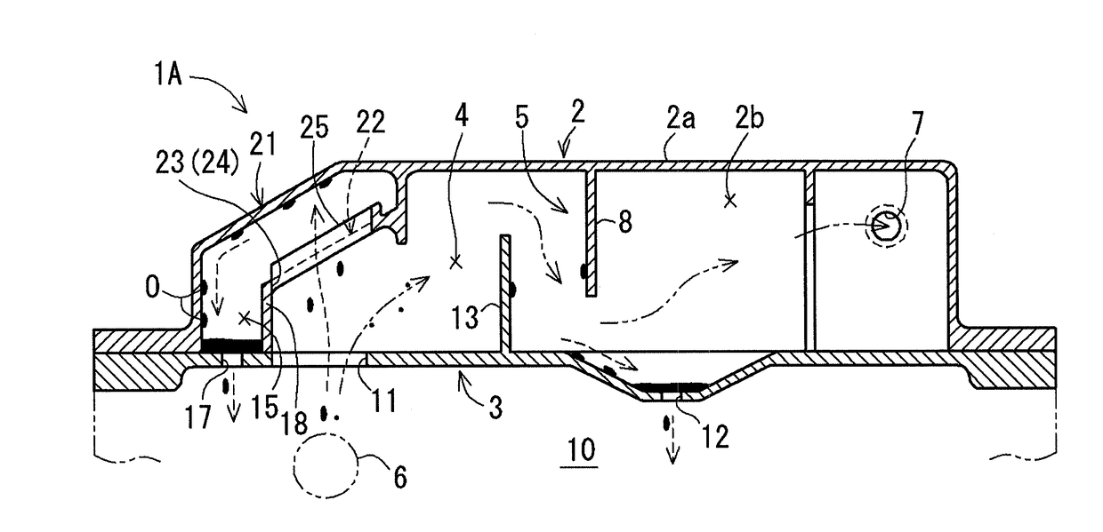
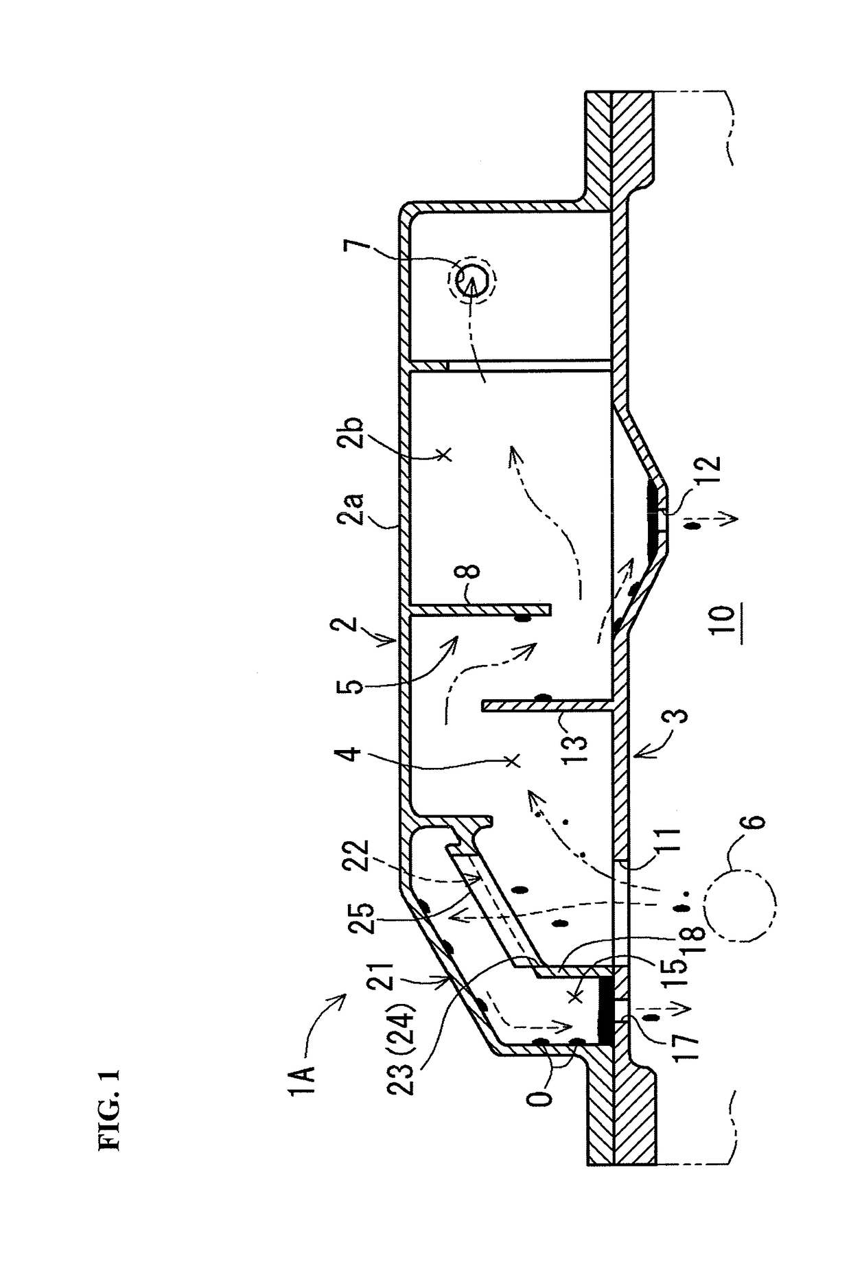
[0046]An oil mist separator 1A according to this Example separates oil from blow-by gas which flows through a gas flow passage 4 that is formed between a cylinder head cover 2 and a baffle plate 3, as shown in FIG. 1. This oil mist separator 1A has a labyrinth type gas-liquid separation structure 5 arranged within the gas flow passage 4.

[0047]The cylinder head cover 2 described above is made of a resin, and formed in a box-like shape with the bottom surface side open. This cylinder head cover 2 includes a ceiling wall 2a and a side wall 2b extending downward from the outer peripheral side of the ceiling wall 2a. Also, the cylinder head cover 2 has formed therein a gas exhaust port 7 which discharges the blow-by gas after oil separation to the outside. This gas exhaust port 7 is arranged on the downstream side of the gas-liquid separation structure 5 in the gas flow passage 4. Further, the cylinder head cover 2 is provided with an upper baffle 8...

example 2

[0059]Next, an oil mist separator 1B according to Example 2 will be explained. Constituent elements of the oil mist separator 1B according to Example 2 that are substantially the same as those of the oil mist separator 1A according to Example 1 described above are given the same reference numerals and will not be described again in detail.

(1) Configuration of Oil Mist Separator

[0060]The oil mist separator 1B according to this Example includes a first guide wall 21 and a second guide wall 22′ as shown in FIGS. 6 and 7. This second guide wall 22′ is provided with a passing part 23′ through which scattered oil flowing from a gas introduction port 11 into a gas flow passage 4 can pass. This passing part 23′ is composed of a mesh-like material 34 such as a metal mesh (see FIG. 7(a)), or composed of a porous plate 36 having a plurality of through holes 35 formed therein (see FIG. 7(b)).

[0061]The opening area of the meshes of the mesh-like material 34 or the opening area of the through hol...

example 3

[0064]Next, an oil mist separator 1C according to Example 3 will be explained. Constituent elements of the oil mist separator 1C according to Example 3 that are substantially the same as those of the oil mist separator 1A according to Example 1 described above are given the same reference numerals and will not be described again in detail.

(1) Configuration of Oil Mist Separator

[0065]The oil mist separator 1C according to this Example includes a first guide wall 21′ and a second guide wall 22 as shown in FIG. 9. This first guide wall 21′ is formed in a dome roof-like shape such that it inclines toward the left and right edge sides of the second guide wall 22 (namely, left and right edge sides in a direction orthogonal to the inclination direction of the second guide wall 22).

(2) Operation and Effect of Oil Mist Separator

[0066]The oil mist separator 1C according to this Example 3 operates in substantially the same manner and provides substantially the same effects as the oil mist sepa...


PUM


Abstract

The oil mist separator separates oil from blow-by gas which flows through a gas flow passage. A chamber, which is partitioned from the gas flow passage including a gas introduction port, is provided between a cylinder head cover and a baffle plate. A first guide wall, which extends with a downward inclination toward the chamber so as to cover the gas introduction port and the chamber, is provided above the gas introduction port and the chamber. A drain hole for discharging the oil within the chamber is formed in the baffle plate.

Description

CROSS-REFERENCE TO RELATED APPLICATIONS[0001]The present application claims priority under 35 U.S.C. § 119 of Japanese Application No. 2017-011494 filed on Jan. 25, 2017, the disclosure of which is expressly incorporated by reference herein in its entirety.BACKGROUND1. Technical Field[0002]The present invention relates to an oil mist separator, and, more specifically, to an oil mist separator which separates oil from blow-by gas which flows through a gas flow passage formed between a cylinder head cover and a baffle plate.2. Related Art[0003]As a conventional oil mist separator, there is generally known an oil mist separator including a cylinder head cover, a baffle plate that closes the bottom surface side of the cylinder head cover, and a gas flow passage formed between the cylinder head cover and the baffle plate, the oil mist separator separating oil from blow-by gas which flows from a gas introduction port formed in the baffle plate into the gas flow passage and flows through t...

Claims


Application Information

Patent Timeline
IPC IPC(8): B01D45/08F01M13/04B01D46/00
CPCB01D45/08F01M13/0416B01D46/0089F01M13/0405F01M2013/0461F01M2013/0422F01M2013/0433F01M2013/0438
Inventor MORISHITA, HIDETOHORIUCHI, YOJIMIYANAGA, NARITSUNE
Owner TOYOTA BOSHOKU KK
Why Eureka
Try Eureka