Robot

a robot and robot arm technology, applied in the field of robots, can solve the problems of increasing the cost of the encoder or the cost of the robot, and achieve the effects of reducing the vibration of the robot arm, high accuracy, and high velocity

Active Publication Date: 2018-07-26
SEIKO EPSON CORP
View PDF0 Cites 3 Cited by
  • Summary
  • Abstract
  • Description
  • Claims
  • Application Information

AI Technical Summary

Benefits of technology

[0032]With this configuration, by controlling an operation of the robot arm based on the detection result (angular velocity, acceleration or the like) of the inertial sensor, it is possible to reduce vibration of the robot arm. Therefore, it is possible to perform the positioning of the tip end portion of the robot arm with high accuracy and at a high velocity.

Problems solved by technology

However, in the related art, when the repetition positioning accuracy of the robot arm is desired to be improved, expensive optical components and capturing elements having performance higher than necessary is used, and as a result, there is a problem that the costs of the encoder or the costs of the robot increase.

Method used


Image

  • Robot
  • Robot
  • Robot

Examples


first embodiment

Robot

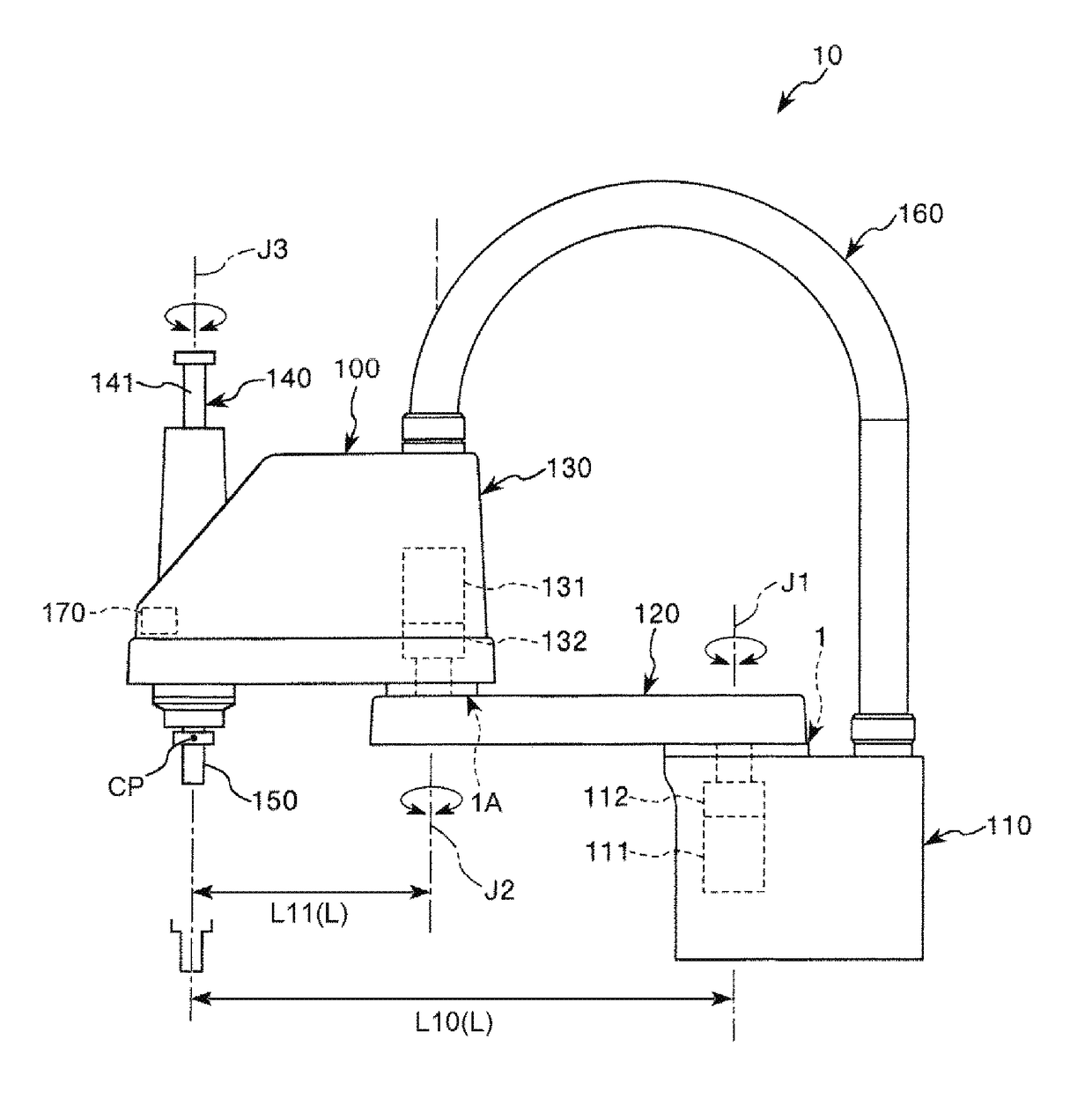
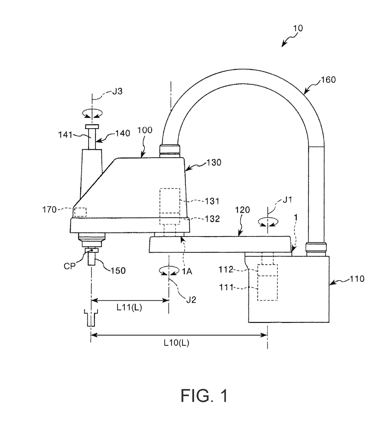
[0059]FIG. 1 is a side view illustrating a robot according to an embodiment of the invention. In addition, hereinafter, for the convenience of the description, an upper side in FIG. 1 is referred to as “up”, and a lower side is referred to as “down”. In addition, a base side in FIG. 1 is referred to as “base end side”, and a side opposite thereto (end effector side) is referred to as “tip end side”. In addition, an upward-and-downward direction of FIG. 1 is referred to as “vertical direction”, and a leftward-and-rightward direction is referred to as “horizontal direction”.

[0060]A robot 10 illustrated in FIG. 1 is a so-called selective compliance assembly robot arm robot (SCARA robot), and for example, the robot 10 is used in a manufacturing process or the like for manufacturing precision equipment or the like, and can perform gripping or transporting of the precision equipment or components.

[0061]As illustrated in FIG. 1, the robot 10 includes a base 110, a first arm 120, a sec...

second embodiment

[0147]FIG. 15 is a view for illustrating the search region (a region which is set regarding the angular velocity of the mark) in the encoder according to a second embodiment of the invention. FIG. 16 is a view for illustrating the search region (a region which is set regarding the moving track of the mark) illustrated in FIG. 15.

[0148]Hereinafter, the second embodiment will be described, but the points different from the above-described embodiment will be focused in the description, and the description of the similar contents will be omitted.

[0149]The embodiment is similar to the above-described first embodiment except that the set range of the search region is different.

[0150]In the above-described first embodiment, the entire effective viewing field region RU is set as the search region RS. In other words, in the above-described first embodiment, the correlating value is calculated by performing the template matching with respect to the pixels of the entire effective viewing field...

third embodiment

[0162]FIG. 17 is a view for illustrating the search region (a region which is set regarding the angular velocity and the angular acceleration of the mark) in the encoder according to a third embodiment of the invention.

[0163]Hereinafter, the third embodiment will be described, but the points different from the above-described embodiment will be focused in the description, and the description of the similar contents will be omitted.

[0164]The embodiment is similar to the above-described first embodiment except that the set range of the search region is different.

[0165]In the above-described second embodiment, when setting the search region RS, since only the angular velocity of the immediately previous first arm 120 predicted from the information related to the two past rotation angles θ (θ11 and θ12) is used, it is necessary to set the search region RS having the size regarding the maximum value of the variation amount Δθ of the angular velocity.

[0166]In the embodiment, when setting ...


PUM


Abstract

A robot includes: a base; a robot arm rotatably provided around a rotation axis relative to the base; a mark which rotates in accordance with rotation of the robot arm; a capturing element which captures the mark; a memory which stores a reference image therein; and a determination section which determines a rotation state of the robot arm by template matching by subpixel estimation using the reference image and an image captured by the capturing element, in which a relationship of 2R/B≤L/X≤100R/B is satisfied when a viewing field size per one pixel of the capturing element is B, a distance between the rotation axis and the center of the mark is R, the maximum distance between the rotation axis and a tip of the robot arm is L, and repetition positioning accuracy of the tip of the robot arm is X.

Description

BACKGROUND1. Technical Field[0001]The present invention relates to a robot.2. Related Art[0002]For example, in a robot including a robot arm having a rotatable joint portion, in general, a rotation state, such as a rotation angle, a rotation position, the number of rotations, and a rotation velocity, of the joint portion is detected by an encoder, and driving of the joint portion is controlled based on the detection result.[0003]For example, the encoder described in JP-A-63-187118 reads a code plate on which a numerical value pattern, such as a gray code, and a stripe-like pattern, are formed by a capturing element, and detects a position from the read numerical value pattern and the stripe-like pattern.[0004]In order to improve repetition positioning accuracy, such as repetition position accuracy of the robot arm, for example, in a case of using the encoder described in JP-A-63-187118, it is necessary to increase a magnification of an optical component provided between the pattern ...

Claims


Application Information

Patent Timeline
Patent Type & Authority Applications(United States)
IPC IPC(8): B25J13/08G01P3/38
CPCB25J13/088G01P3/38Y10S901/47Y10S901/02B25J9/1664B25J9/1671B25J9/1697
Inventor TOKUSHIMA, DAIKI
Owner SEIKO EPSON CORP
Why Eureka
Try Eureka