Electric hair cutter

Active Publication Date: 2018-07-26
PANASONIC INTELLECTUAL PROPERTY MANAGEMENT CO LTD
View PDF49 Cites 3 Cited by
  • Summary
  • Abstract
  • Description
  • Claims
  • Application Information

AI Technical Summary

Benefits of technology

The invention is an electric hair cutter that reduces the noise generated while in use. It includes a motion conversion mechanism that converts the rotary motion of the electric motor into linear motion. The output portion of the mechanism is coupled to a movable blade, which performs thereciprocating linear motion. The mechanism also includes an elastic deformation part that restricts the motion of the motion transmission part, which is caused by motion components that differ from the output direction. This invention aims to provide a more efficient and effective electric hair cutter with reduced noise.

Problems solved by technology

Such interference of the link 912A with the guides 912C may generate a loud noise.

Method used


Image

  • Electric hair cutter
  • Electric hair cutter
  • Electric hair cutter

Examples


embodiments

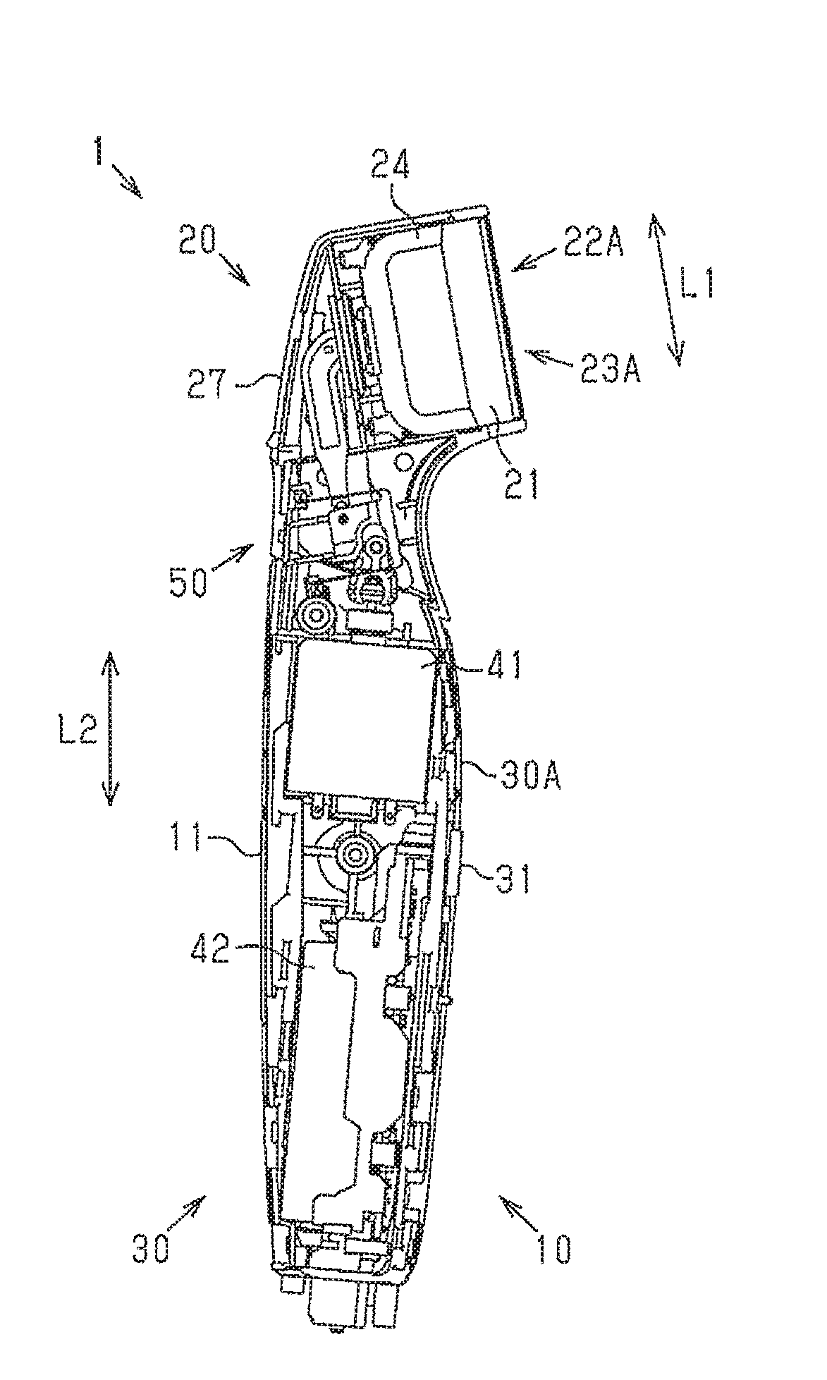
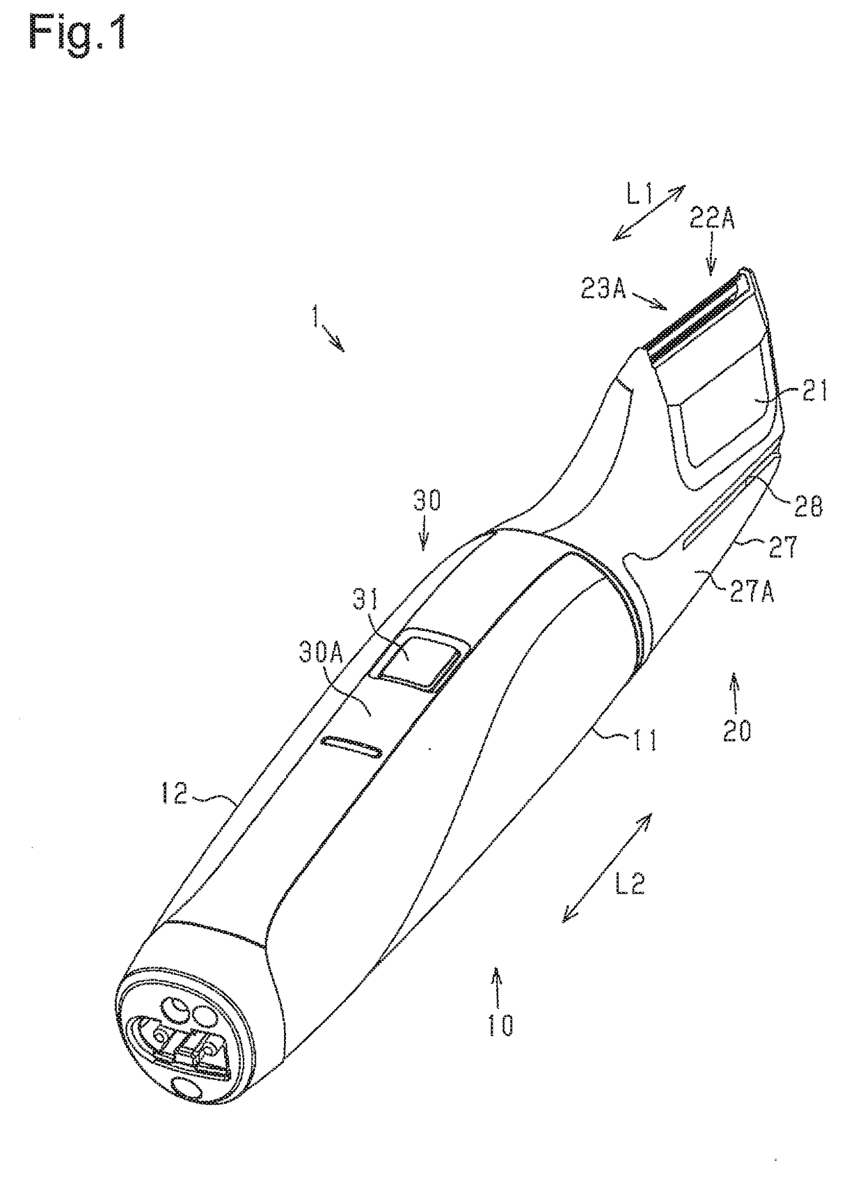
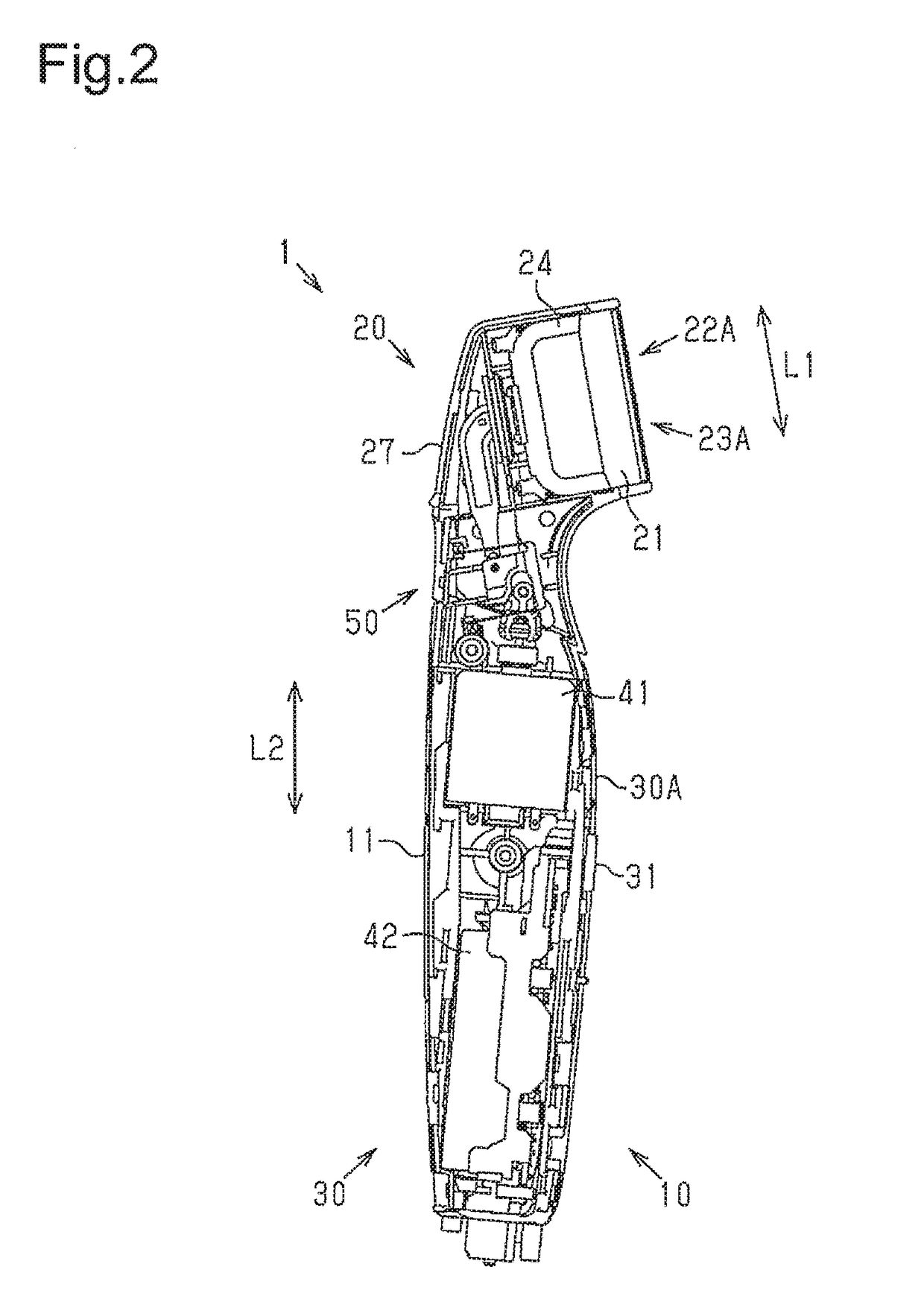
[0031]FIG. 1 shows an outer appearance of an electric hair cutter 1. The electric hair cutter 1 has a size suitable for cutting, for example, beard or head hair. One example of the electric hair cutter 1 is a trimmer. The electric hair cutter 1 includes a body 10 and a blade unit 21. The body 10 accommodates various components of the electric hair cutter 1. The blade unit 21 functions to cut hair. The blade unit 21 is attached to the body 10 in a removable manner.

[0032]The body 10 includes a case 11 and a cover 12. The various components of the electric hair cutter 1 are accommodated in the case 11 (refer to FIG. 2). The cover 12 is attached to the case 11 in a removable manner. When the various components of the electric hair cutter 1 are accommodated in the case 11 and the cover 12 is attached to the case 11, the body 10 is formed.

[0033]The electric hair cutter 1 includes a head 20 and a grip 30. The head 20 includes the blade unit 21 and a support unit 27. The blade unit 21 is at...

modified examples

[0076]The above description illustrates embodiments of an electric hair cutter according to the present invention and is not intended to be restrictive. The embodiments may be modified as follows. Further, two or more of the modified examples may be combined.

[0077]The first conversion portion 60 and the second conversion portion 70 may have any relationship. In one example, the first conversion portion 60 and the second conversion portion 70 are configured so that the imaginary line XL intersects with the output direction SD. In this example, it is preferred that the angle formed by the imaginary line XL and the output direction SD be set to be close to 0°.

[0078]The first axis CL1 may be located at any position. In a first example, the first axis CL1 is located closer to the movable blade 23A than the two first elastic parts 75A. In a second example, the first axis CL1 is located closer to the electric motor 41 than the two second elastic parts 75B. In a third example, the first axi...


PUM


Abstract

An electric hair cutter includes a motion conversion mechanism that converts rotary motion of an output shaft of an electric motor into reciprocating linear motion and a movable blade driven by reciprocating linear motion of the motion conversion mechanism. The motion conversion mechanism includes a first conversion portion, converting rotary motion of the output shaft into reciprocating rotary motion about a first axis, a second conversion portion, converting the reciprocating rotary motion into reciprocating linear motion, and an output portion, coupling the second conversion portion to the movable blade. The second conversion portion includes a motion transmission part, coupling the first conversion portion to the output portion, and an elastic deformation part coupled to the motion transmission part to restrict motion of the motion transmission part caused by motion components differing from a motion component in an output direction so that the motion transmission part linearly reciprocates.

Description

BACKGROUND OF THE INVENTION[0001]The present disclosure relates to an electric hair cutter.[0002]One example of a known electric hair cutter, which is driven by electric power to cut body hair such as beard, includes an electric motor having an output shaft and a motion conversion mechanism that converts rotary motion of the output shaft of the electric motor into reciprocating linear motion. The reciprocating linear motion drives a movable blade with respect to a fixed blade. Japanese Laid-Open Patent Publication No. 2013-66548 discloses one example of such an electric hair cutter. As shown in FIG. 12, an electric hair cutter 900 includes a motion conversion mechanism 910 that includes a first conversion portion 911, a second conversion portion 912, and an output portion 913.[0003]The first conversion portion 911 converts rotary motion of an output shaft 921 of an electric motor 920 into reciprocating linear motion in a direction intersecting with the axis of the output shaft 921. ...

Claims


Application Information

Patent Timeline
IPC IPC(8): B26B19/28B26B19/38B26B19/10F16H25/20
CPCB26B19/28B26B19/3846B26B19/3853B26B19/105F16H25/20B26B19/08B26B19/3806B26B19/06
Inventor WANG, WEIYAMAGUCHI, TAKASHIYAN, QINGHUI
Owner PANASONIC INTELLECTUAL PROPERTY MANAGEMENT CO LTD
Why Eureka
Try Eureka