Encapsulated agent, method of manufacturing encapsulated agent, and variable viscosity fluid
a technology of encapsulated agents and encapsulated liquids, which is applied in the field of encapsulated agents, method of manufacturing encapsulated agents, and variable viscosity fluids, can solve the problems of difficult to collect shale gas from the earth, and achieve superior viscosity variation properties, superior viscosity-reducing functions, and superior viscosity-reducing functions
- Summary
- Abstract
- Description
- Claims
- Application Information
AI Technical Summary
Benefits of technology
Problems solved by technology
Method used
Image
Examples
modification examples
1-5. Modification Examples
[0164]Regarding the configuration of the encapsulated agent according to the embodiment of the invention, various modification examples are providable.
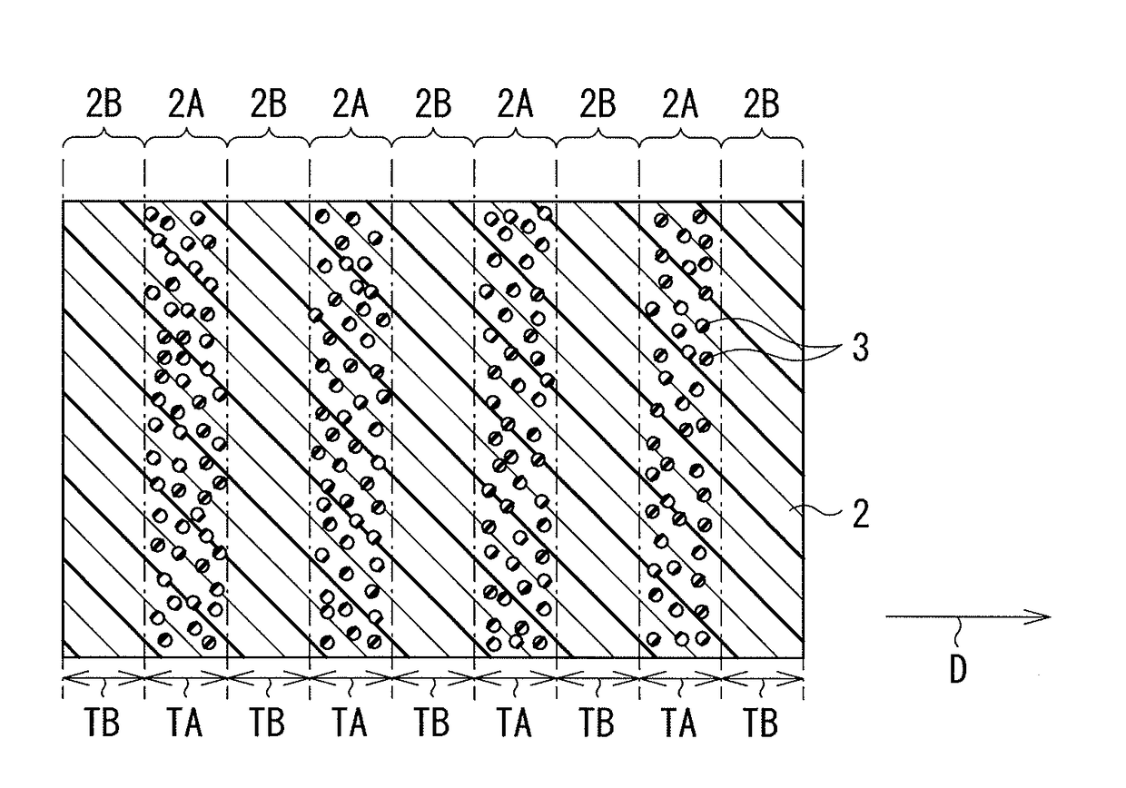
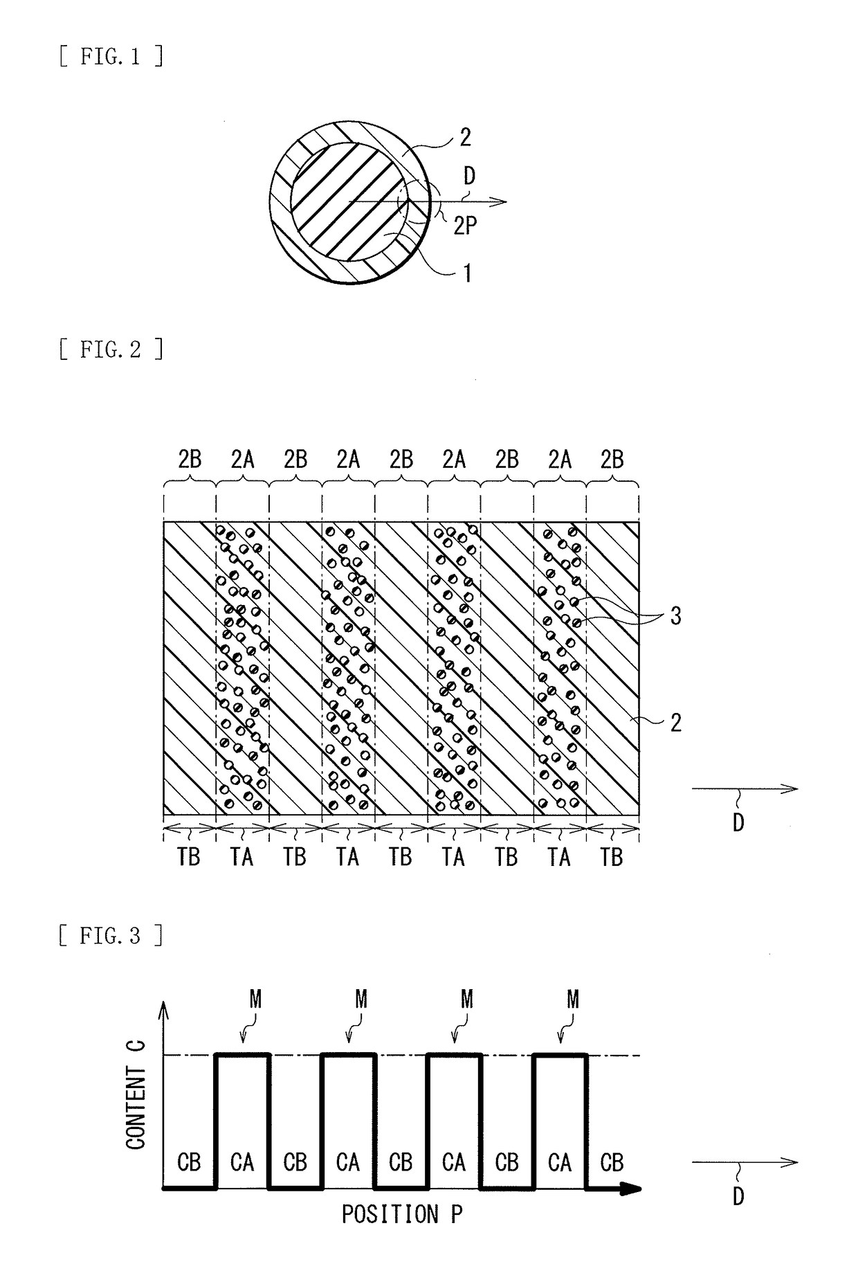
[0165]Specifically, as long as the plurality of particulate substances 3 are distributed in such a manner that the content C of the plurality of particulate substances is allowed to have one or more local maxima M in the outer part 2 (the direction D), the configuration of the outer part 2 is not limited to each of the configurations illustrated in FIGS. 2 and 3, and the outer part 2 may have any other configuration. In such a case, it is also possible to obtain similar effects.
first modification example
[0166]FIG. 6 illustrates a cross-sectional configuration of an encapsulated agent (the outer part 2) according to a first modification example, and corresponds to FIG. 2. FIG. 7 illustrates the distribution of the plurality of particulate substances 3 in the outer part 2 illustrated in FIG. 6, and corresponds to FIG. 3.
[0167]In a case where the small-content region 2B does not include the plurality of particulate substances 3, the large-content regions 2A and the small-content regions 2B may be disposed alternately in this order from the side close to the central part 1 in the outer part 2, as illustrated in FIGS. 6 and 7. In this case, the large-content region 2A is disposed at a position closest to the central part 1. It is to be noted that the large-content region 2A may be disposed, or the small-content region 2B may be disposed at a position farthest from the central part 1. Each of FIGS. 6 and 7 illustrates, for example, a case where the large-content region 2A is disposed at ...
second modification example
[0169]FIG. 8 illustrates a cross-sectional configuration of an encapsulated agent (the outer part 2) according to a second modification example, and corresponds to FIG. 2. FIG. 9 illustrates the distribution of the plurality of particulate substances 3 in the outer part 2 illustrated in FIG. 8, and corresponds to FIG. 3.
[0170]The small-content region 2B may include the plurality of particulate substances 3. However, as described above, the content CB of the plurality of particulate substances 3 in the small-content region 2B is set to be smaller than the content CA of the plurality of particulate substances 3 in the large-content region 2A.
[0171]In this case, the small-content regions 2B and the large-content regions 2A may be disposed alternately in this order from the side close to the central part 1 in the outer part 2, as illustrated in FIGS. 8 and 9. In such a case, the small-content region 2B is disposed, at a position closest to the central part 1. It is to be noted that the ...
PUM
 Abstract
Description
Claims
Application Information
 - R&D
- Intellectual Property
- Life Sciences
- Materials
- Tech Scout
- Unparalleled Data Quality
- Higher Quality Content
- 60% Fewer Hallucinations
Browse by: Latest US Patents, China's latest patents, Technical Efficacy Thesaurus, Application Domain, Technology Topic, Popular Technical Reports.
© 2025 PatSnap. All rights reserved.Legal|Privacy policy|Modern Slavery Act Transparency Statement|Sitemap|About US| Contact US: help@patsnap.com


