Electric starter with manual turning function

a technology of electric starter and function, applied in the direction of engine starter, muscle operated starter, gearbox, etc., can solve the problems of manual turning function, casualty or equipment malfunction, and traditional electric starters do not have manual turning function, so as to save space for independent arrangement of turning mechanism, save personnel and equipment, and be safer and more reliable to operate and us

Active Publication Date: 2018-07-26
CHONGQING STARTING POWER UNIT CO LTD
View PDF0 Cites 0 Cited by
  • Summary
  • Abstract
  • Description
  • Claims
  • Application Information

AI Technical Summary

Benefits of technology

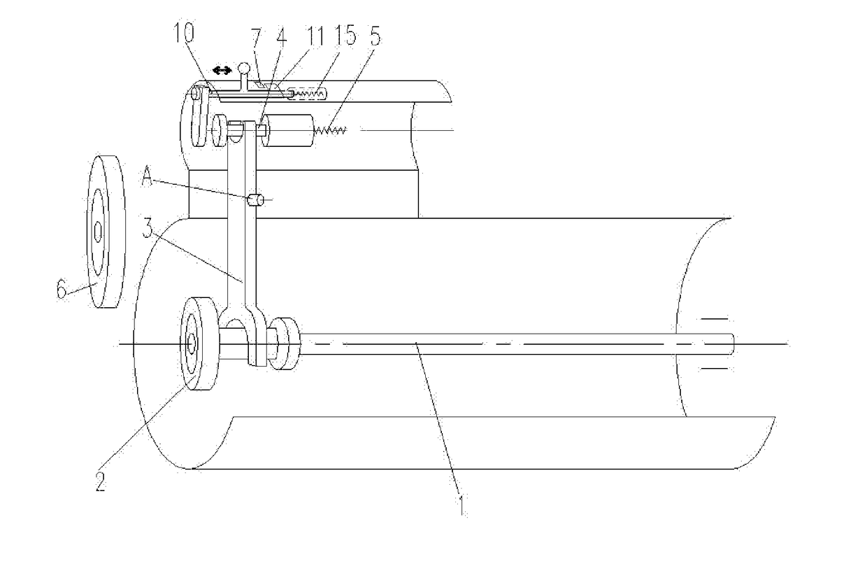
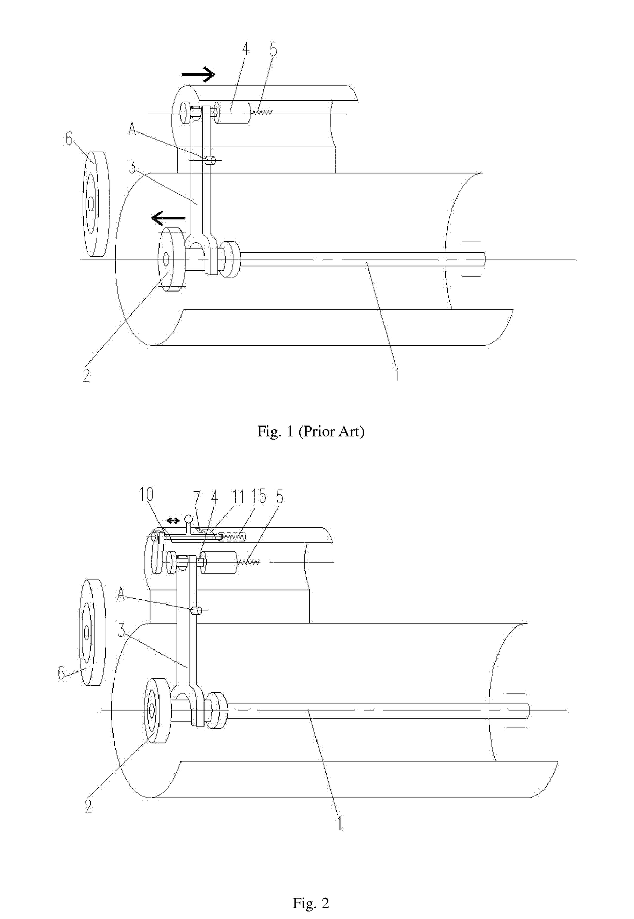
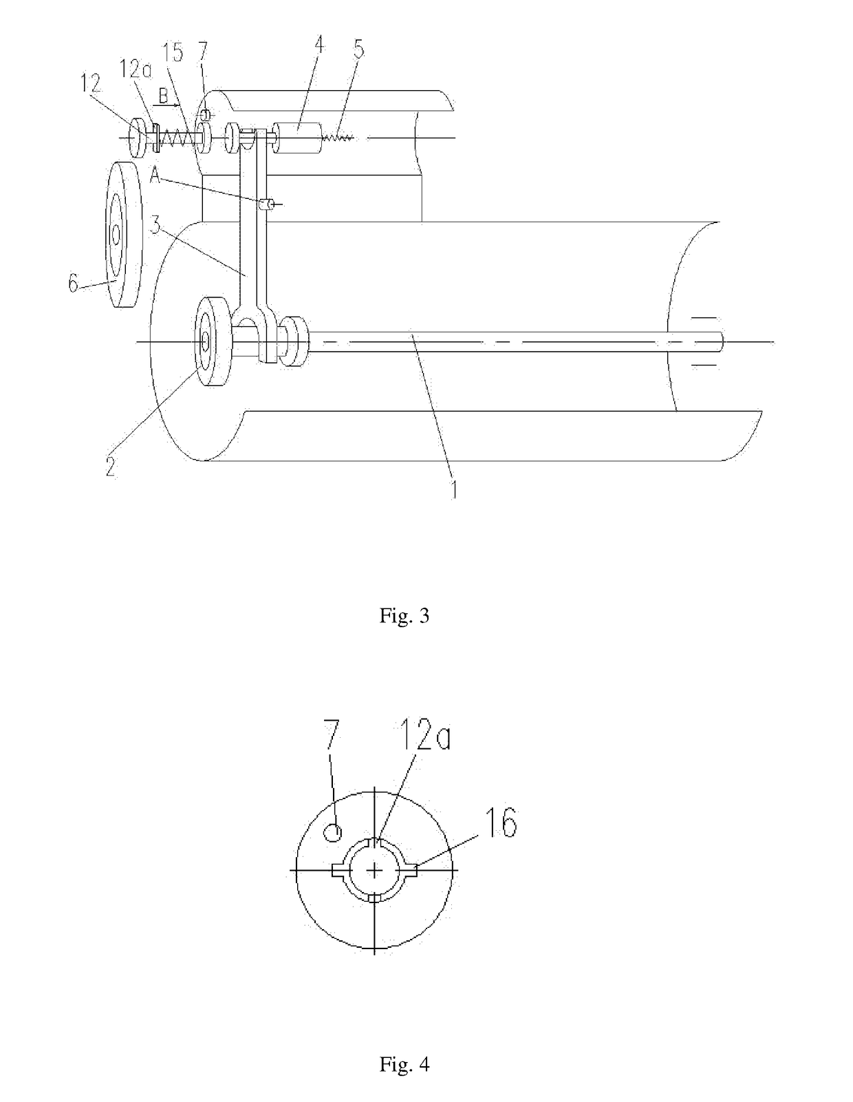
[0011]The present disclosure has following beneficial effects. The gear shifting mechanism and the turning mechanism are integrated to the electric starter, so that a traditional electric starter can have a new manual turning function. There is no need to refit a housing of a traditional motor flywheel, and space for independently arranging the turning mechanism is saved. The normally closed switch in the electric starter serves as a normally closed conversion protection device, so that a starting function and a turning function cannot be achieved simultaneously and no harm will be brought about to personnel and equipment. Meanwhile, the gear shifting mechanism has an automatical return function after being unlocked, and the transmission mechanism of the turning mechanism also has an automatical return function, so that it is more convenient, safer and more reliable to operate and use the electric starter. Double safety can be achieved in combination with the normally closed switch. Besides, by manually turning, the flywheel gear of the motor can be positioned conveniently and precisely during overhaul and maintenance, so that working efficiency can be improved and potential safety hazards of a traditional manner can be eliminated.

Problems solved by technology

However, when the motor needs to be turned before work, the flywheel gear 6 is required to rotate at a low speed, but an existing electric starter can only realize high-speed rotation of the flywheel gear 6 and does not have a manual turning function.
Traditional electric starters do not have the manual turning function.
Although low-speed precise rotation can be realized, there are potential safety hazards (for example, if an operator forgets to take down the steel crowbar, the steel crowbar might be popped out when the flywheel gear of the motor rotates, which will cause casualty or equipment malfunction), and efficiency thereof is low.

Method used


Image

  • Electric starter with manual turning function
  • Electric starter with manual turning function
  • Electric starter with manual turning function

Examples


embodiment 1

of the Turning Mechanism

[0032]As shown in FIG. 6, an opening 8 for insertion of a wrench or a sleeve-like turning tool is provided in the housing of the turning mechanism. The main shaft 1 is indirectly driven to rotate by the turning mechanism via a transmission mechanism, and two bevel gears engaged with each other are used for transmission of the transmission mechanism. The opening 8 is arranged on a top of the housing of the turning mechanism. A turning shaft 9 is fixedly connected to a driving gear of the bevel gears and is driven to rotate by a turning tool. A return spring is used as a second return component. When the turning shaft 9 is pressed, the turning shaft 9 moves axially downwards, and the return spring is compressed, so that a driving portion of the transmission mechanism engages with a driven portion thereof. When pressure on the turning shaft 9 is relieved, the second return component returns to an original state, and the driving portion of the transmission mechan...

embodiment 2

of the TURNING mechanism

[0033]A structure of a turning mechanism as shown in FIG. 7 is basically similar to a structure as shown in FIG. 6. A difference of the structure as shown in FIG. 7 from the structure as shown in FIG. 6 is that a worm-gear is used for transmission of the transmission mechanism. The main shaft 1 is also indirectly driven to rotate by the transmission mechanism.

embodiment 3

of the Turning Mechanism

[0034]A structure of a turning mechanism as shown in FIG. 8 is basically similar to the structure as shown in FIG. 6. Differences of the structure as shown in FIG. 8 from the structure as shown in FIG. 6 lie in that, two cylindrical gears are used for transmission of the transmission mechanism, and an opening 8 is arranged on a right side of the housing of the turning mechanism. The main shaft 1 is also indirectly driven to rotate by the transmission mechanism.


PUM


Abstract

Disclosed is an electric starter with a manual turning function. A main shaft, a drive gear mechanism, a shift fork, an electromagnetic relay guide rod and a first return spring are arranged in a housing of the electric starter. A gear shifting mechanism comprises a force receiving component which extends out of the housing of the electric starter and serves as an external force applying point so as to promote the electromagnetic relay guide rod to move rightwards, a normally closed switch for cutting off a power supply of the electric starter when the force receiving component moves to an extreme position, a positioning component for locking the force receiving component when the force receiving component moves to the extreme position, and a first return component which enables the force receiving component to automatically returns to an original state when the force receiving component is unlocked. The main shaft is indirectly driven to rotate by the turning mechanism via a transmission mechanism or directly driven to rotate by the turning mechanism via a turning tool. An improvement is made to a structure of a traditional electric starter without affecting existing functions thereof, i.e., a function of manual turning is added. Therefore, a flywheel gear of a motor can be precisely positioned during maintenance so as to improve efficiency and eliminate potential safety hazards.

Description

FIELD OF THE INVENTION[0001]The present disclosure relates to an electric starter for detection and maintenance of a motor. A manual turning function is added to an existing electric starter, and the present disclosure belongs to the technical field of mechanical structure.BACKGROUND OF THE INVENTION[0002]Most existing motors are assembled with an electric starter. As shown in FIG. 1, a main shaft 1, a drive gear mechanism 2, a shift fork 3, an electromagnetic relay guide rod 4 and a first return spring 5 are arranged in a housing of the electric starter. The electromagnetic relay guide rod 4 moves rightwards, which promotes the shift fork 3 to rotate clockwise around a hinge joint A. An upper end of the shift fork 3 compresses the first return spring 5, and a lower end of the shift fork 3 enables the main shaft 1 to move leftwards so that the drive gear mechanism 2 engages with a flywheel gear 6 of a motor. Then, the main shaft 1 promotes the flywheel gear 6 to rotate at a high spe...

Claims


Application Information

Patent Timeline
Patent Type & Authority Applications(United States)
IPC IPC(8): F02B77/08F02N11/08F02N11/10F02N15/06F16H35/18
CPCF02B77/083F02N11/0851F02N11/101F02N15/067F16H35/18F02N15/062F02N2200/04F02B77/00F02N1/00F02N11/00F02N11/106F02N11/108F02N1/02F02N2250/00F02N1/005F02N11/10F02N11/08
Inventor LIU, SHUQUANLIN, YANGGUANGZHU, DA'AN
Owner CHONGQING STARTING POWER UNIT CO LTD
Why Eureka
Try Eureka