Subsea centrifugal compressor with horizontal shaft and with only one axial thrust bearing

a centrifugal compressor and horizontal shaft technology, applied in the direction of pump installation, non-positive displacement fluid engine, liquid fuel engine components, etc., can solve the problems of increasing the number of compression stages, and affecting the efficiency of the motor compressor

Inactive Publication Date: 2018-07-26
THERMODYN
View PDF2 Cites 2 Cited by
  • Summary
  • Abstract
  • Description
  • Claims
  • Application Information

AI Technical Summary

Benefits of technology

[0014]A further purpose of embodiments of the present invention is to provide a centrifugal compressor unit for subsea applications in which the problem of axial displacement of the bladed wheels mounted on the compressor shaft are overcome.

Problems solved by technology

However, this type of arrangement in which the rotor is axially supported by one thrust bearing has the disadvantage that the coupling between the rotor of the motor and the compressor shaft may be prejudicial to the accuracy of the axial position of the rotating elements of the compressor which may impact the motor compressor efficiency, in particular during transient phases.
This problem may in particular incur at high loads, due to a thermal expansion of the compressor shaft driven by the motor means and may arise for compressor units having a high pressure ratio, namely above 3, and having an increased number of compression stages, equal or higher than 3.
Such an arrangement does not permit, however, to increase the number of the compression stages such that the motor compressor unit cannot be equipped with more than three compression stages.

Method used


Image

  • Subsea centrifugal compressor with horizontal shaft and with only one axial thrust bearing
  • Subsea centrifugal compressor with horizontal shaft and with only one axial thrust bearing
  • Subsea centrifugal compressor with horizontal shaft and with only one axial thrust bearing

Examples


Embodiment Construction

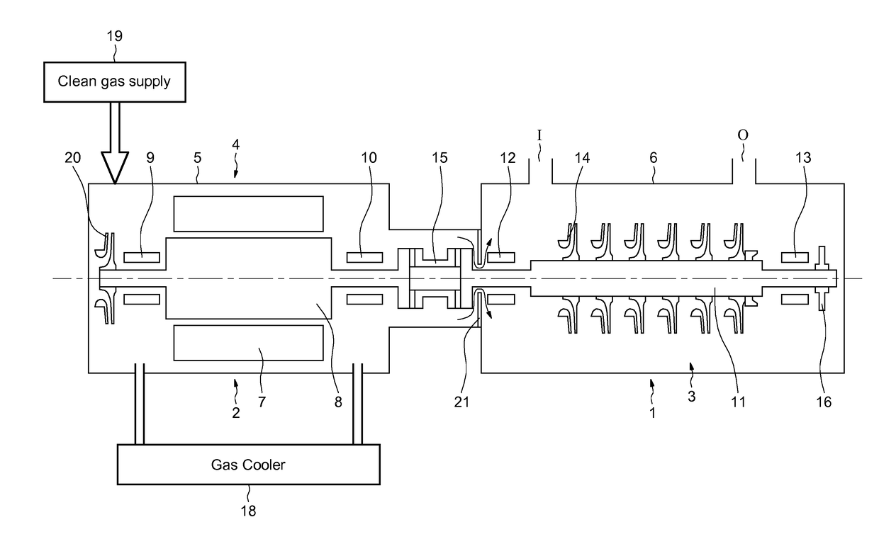
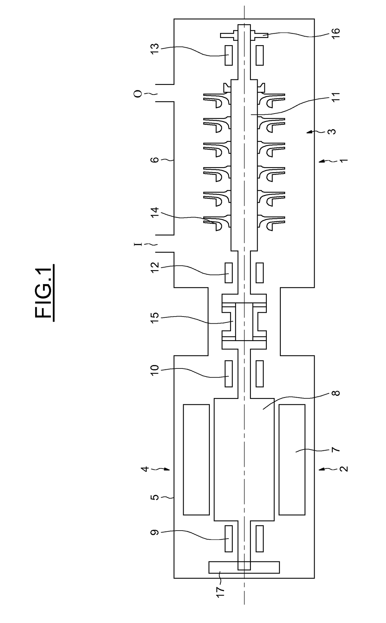
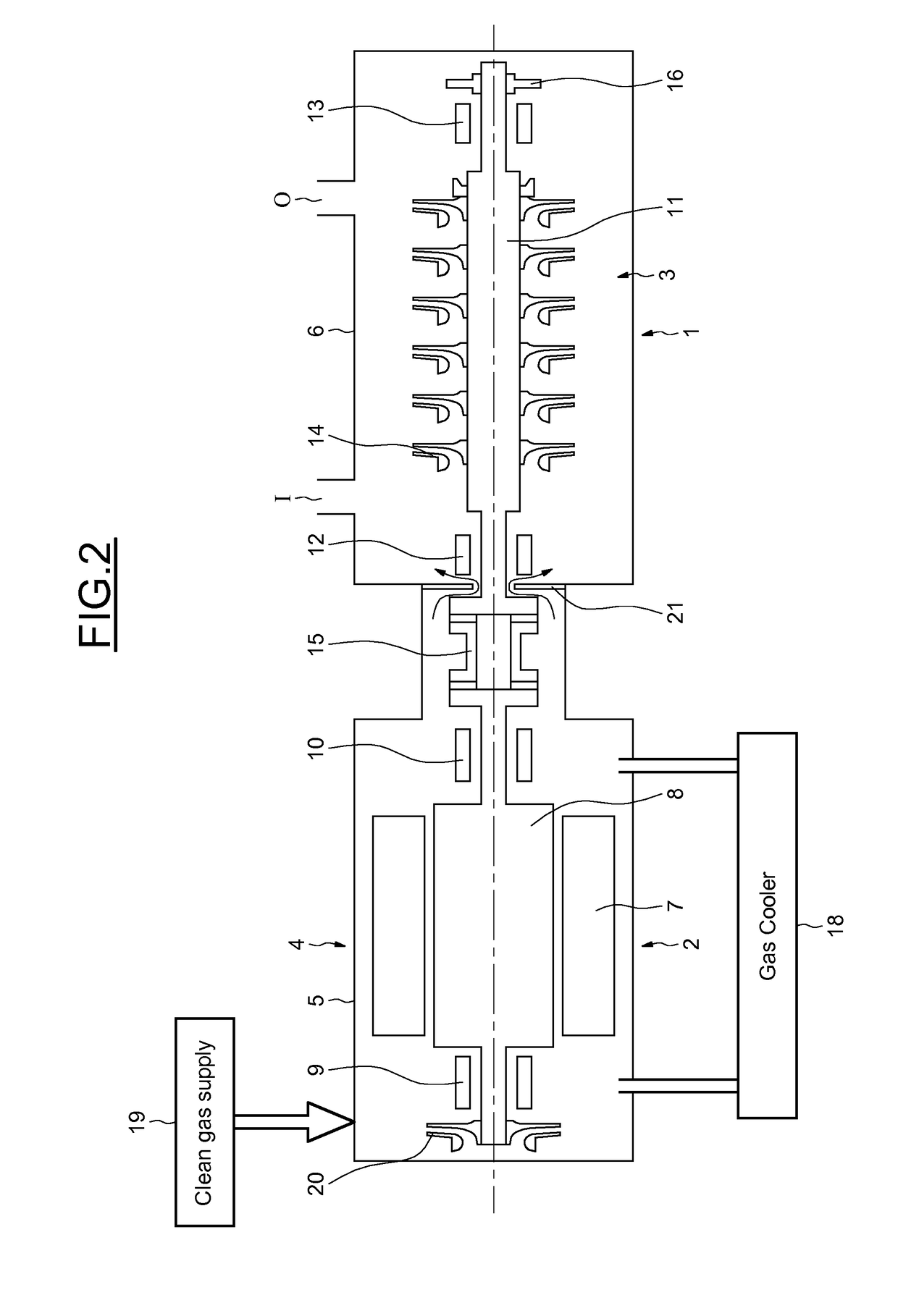
[0029]FIG. 1 shows a centrifugal compressor unit 1 according to embodiments of the invention, for subsea applications, having a motor 2 and one or more compressor(s) 3 mounted in a common casing 4 leak tight to the gas manipulated by the compressor 3.

[0030]The casing 4 comprises two casing elements fixed together by appropriate attachment means, the one, denoted by numeral reference 5, accommodating the motor 2 and the other, denoted by reference 6, accommodating the compressor.

[0031]The casing elements are intended to provide support and protection for the motor and the compressor, respectively. As illustrated, the casing 2 is provided with a gas inlet orifice I facing the first compression stage of the compressor and an outlet orifice O facing the last compression stage.

[0032]In operation, the casing element assembly is intended to be pressurized and immersed and is arranged on a base such that the compressor unit is arranged horizontally.

[0033]In the exemplary embodiment, the mot...


PUM


Abstract

A centrifugal compressor unit including a motor having a rotor, at least one compressor having a shaft driven by the rotor; and a set of bladed wheels fitted on the driven shaft, the motor and the compressor being mounted in a common watertight casing. It further includes cooling means for cooling the motor, the cooling means having a gas cooler outside the casing. In operation, the motor, the compressor and the casing having the motor and the compressor are arranged horizontally, one axial thrust bearing only being provided on a compressor side.

Description

BACKGROUND OF THE INVENTION[0001]Embodiments of the invention relate to a turbocompressor or a motor compressor, and particularly to an integrated motor compressor unit.[0002]More particularly, embodiments of the present invention relate to a motor compressor unit for subsea applications.[0003]Motor compressor units of the integrated type comprise a motor means, generally an electric drive motor, and a compressor having one or more compression stages, depending on the applications, the motor means and the compressor being mounted in a common casing that is sealed against the gas handled by the compressor unit.[0004]Each compression stage comprises a bladed impeller mounted on a shaft driven by a rotor, which is driven by the motor means.[0005]According to the state of the art, when used under special operating conditions, especially for underwater operations, the motor compressor is usually arranged vertically to facilitate draining of the interior of the casing.[0006]A compressor u...

Claims


Application Information

Patent Timeline
Patent Type & Authority Applications(United States)
IPC IPC(8): F04D29/051F04D25/06F04D29/058F04D17/12F04D29/58F04D29/42F04D29/10F04D29/054
CPCF04D29/051F04D25/0686F04D29/058F04D17/122F04D29/5826F04D29/4206F04D29/102F04D29/054F04D29/5806
Inventor LABOUBE, PIERRE GEORGESCAMATTI, MASSIMOESPOSITO, ROBERTO
Owner THERMODYN
Why Eureka
Try Eureka