Welding tool for side lower plate and side flat plate of armored car

A technology for flat plate welding and armored vehicles, applied in the field of fixtures, can solve the problems of insufficient connection strength at the welding point, complex and long manufacturing process, poor process stability, etc., to improve the degree of welding automation, improve welding quality, and large clamping area. Effect

Pending Publication Date: 2021-06-22
江苏锐成机械有限公司
View PDF0 Cites 0 Cited by
  • Summary
  • Abstract
  • Description
  • Claims
  • Application Information

AI Technical Summary

Problems solved by technology

[0002] The steel plate used in the explosion-proof armored vehicle body is relatively thick, and the steel plates between different positions are welded to form the car body. The welding generally adopts the form of opening a bevel at the welding place and then performing electric welding. The electric welding can be done manually or by a welding robot. This welding The disadvantage is that due to the thick steel plate, there will be insufficient connection strength at the welding place. Some welding positions cannot be completed by welding robots and need to be completed manually. In addition, the process stability of the electric welding process is slightly poor, and a flaw detection process is often required. In this way, the manufacturing process of the entire car body is complicated and lengthy, and it is a task to seek a car body processing method with a high degree of automation and good welding quality.

Method used


Image

  • Welding tool for side lower plate and side flat plate of armored car
  • Welding tool for side lower plate and side flat plate of armored car
  • Welding tool for side lower plate and side flat plate of armored car

Examples


Embodiment Construction

[0020] In order to make the purpose, technical solutions and advantages of the embodiments of the present invention clearer, the technical solutions in the embodiments of the present invention will be clearly and completely described below in conjunction with the drawings in the embodiments of the present invention. Obviously, the described embodiments It is a part of the embodiments of the present invention, rather than all of them. Based on the embodiments of the present invention, all other embodiments obtained by those of ordinary skill in the art without creative work all belong to the protection scope of the present invention .

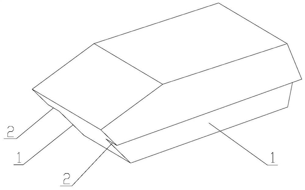
[0021] attached figure 1 Shown is that the side lower plate 1 and the side plate 2 required to be welded by the present invention are located on the armored vehicle body, the side lower plate includes a left lower plate and a right lower plate, and the side plate includes a left plate and a right plate.

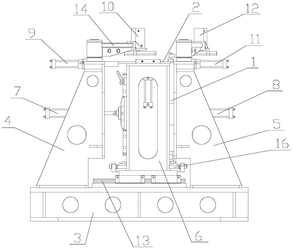
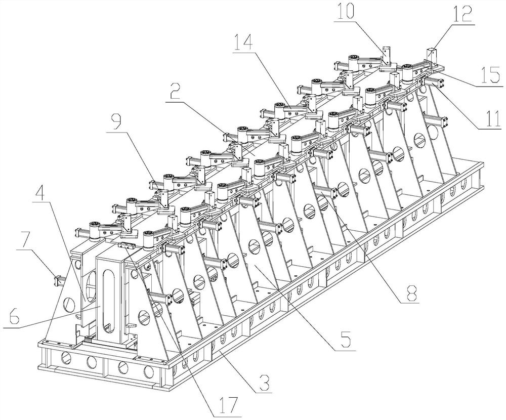
[0022] combined with figure 2 with 3...


PUM


Abstract

The invention relates to the technical field of tool clamps, in particular to a welding tool for a side lower plate and a side flat plate of an armored car. The welding tool which is high in automation degree and good in welding quality under a friction stir welding method is provided, a vertical left clamping plate and a vertical right clamping plate are arranged on a tool bottom plate, an inner supporting frame moving left and right is arranged between the left clamping plate and the right clamping plate, the left side face of the inner supporting frame and the left clamping plate form a left side lower plate clamping space, the right side face of the inner supporting frame and the right clamping plate form a right side lower plate clamping space, the top face of the inner supporting frame is a bearing face for a left side flat plate or a right side flat plate, the left clamping plate is provided with a first oil cylinder pushing the inner supporting frame to move rightwards to clamp the right side lower plate, the right clamping plate is provided with a second oil cylinder pushing the inner supporting frame to move leftwards to clamp the left side lower plate, the top of the left clamping plate is provided with a third oil cylinder pressing a right side flat plate on the top face of the inner supporting frame rightwards and a fourth oil cylinder pressing downwards, and the top of the right clamping plate is provided with a fifth oil cylinder for leftwards pressing a left side flat plate on the top surface of the inner supporting frame and a sixth oil cylinder for downwards pressing.

Description

technical field [0001] The invention relates to the technical field of tool fixtures, in particular to a welding tool for the side lower plate and side plate of an armored vehicle. Background technique [0002] The steel plate used in the explosion-proof armored vehicle body is relatively thick, and the steel plates between different positions are welded to form the car body. The welding generally adopts the form of opening a bevel at the welding place and then performing electric welding. The electric welding can be done manually or by a welding robot. This welding The disadvantage is that due to the thick steel plate, there will be insufficient connection strength at the welding place. Some welding positions cannot be completed by welding robots and need to be completed manually. In addition, the process stability of the electric welding process is slightly poor, and a flaw detection process is often required. Like this, the manufacturing process of whole car body is compl...

Claims


Application Information

Patent Timeline
Patent Type & Authority Applications(China)
IPC IPC(8): B23K20/12B23K20/26
CPCB23K20/12B23K20/122B23K20/126B23K20/129B23K20/26
Inventor 谈海强周琦
Owner 江苏锐成机械有限公司
Why Eureka
Try Eureka