Magnetic coupling

a technology of magnetic coupling and coupling rod, which is applied in the direction of magnetic bodies, magnetic circuits characterised by magnetic materials, machines/engines, etc., can solve the problems of high assembly complexity, high manufacturing cost, and inability to manufacture such rotors, etc., and achieves low construction cost, high transmission efficiency, and small constructional size

Active Publication Date: 2018-07-26
GRUNDFOS HLDG
View PDF4 Cites 2 Cited by
  • Summary
  • Abstract
  • Description
  • Claims
  • Application Information

AI Technical Summary

Benefits of technology

[0007]Against this background, it is an object of the present invention, to provide a magnetic coupling of the initially mentioned type, which on the one hand is inexpensively manufacturable and on the other hand with a comparatively small constructional size can transmit high moments, and with which the magnetic material can be easily recycled as the case maybe.

Problems solved by technology

The manufacture of such rotors is comparatively cumbersome, since the permanent magnets are to be reliably fixed in the respective rotors.
The coupling described there however is extremely cumbersome with regard to the construction, since the permanent magnets have a special shape adapted to the respective diameter of the rotors and on the one hand are complex with regard to manufacture and on the other hand are even more complex with regard to assembly.
Moreover, there is also a problem with recycling with the permanent magnets of the couplings of the previously mentioned type.

Method used


Image

  • Magnetic coupling
  • Magnetic coupling
  • Magnetic coupling

Examples


Embodiment Construction

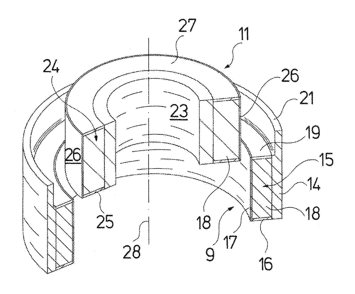
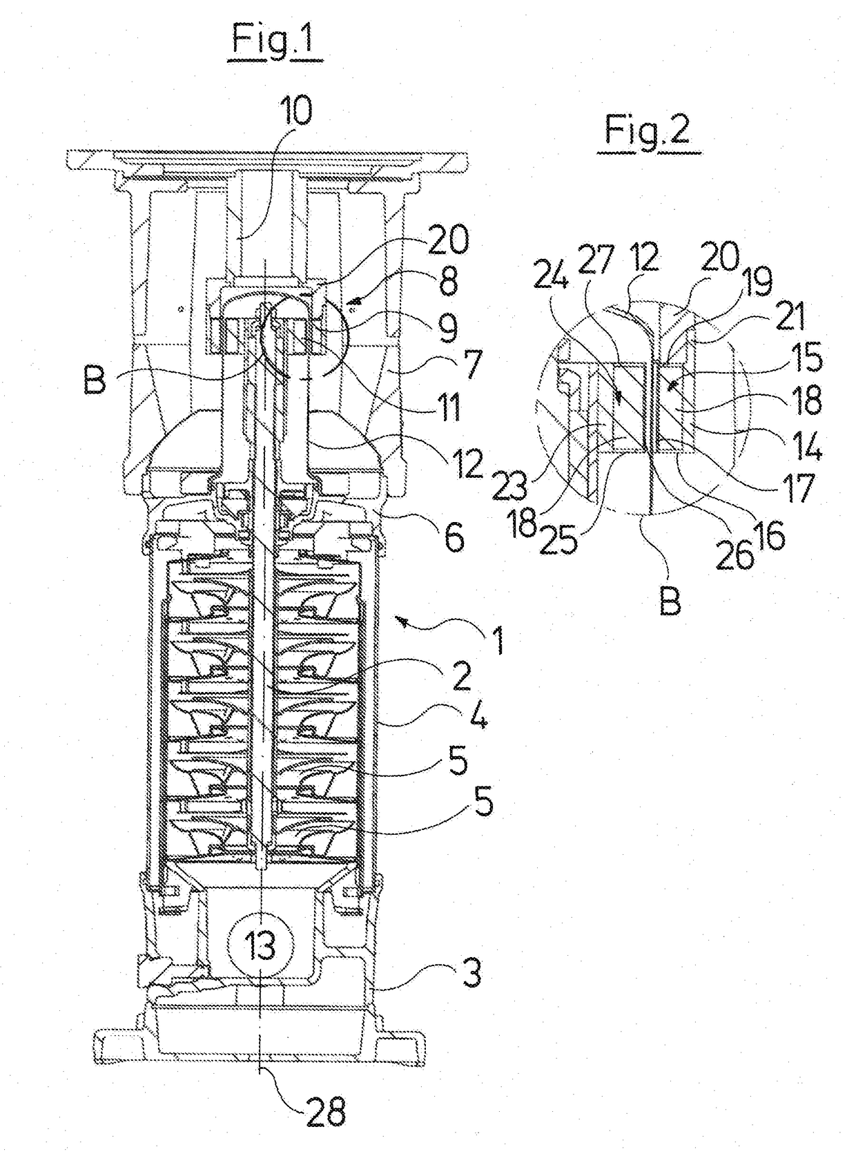
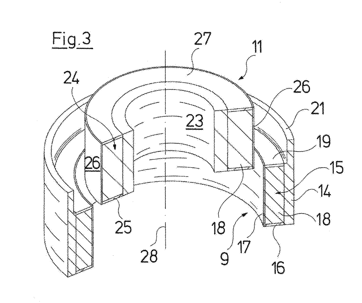
[0041]Referring to the drawings, the centrifugal pump represented in FIG. 1 is a multistage centrifugal pump 1 which in some features of the construction corresponds to known centrifugal pumps of the type Grundfos CR. Hereby, it is the case of a pump which is operated with a vertical shaft 2, and is with a foot 3 which stands on the floor and onto which a middle section closed off to the outside by a jacket 4 connects, in which section impellers 5 are seated on the shaft 2. The jacket 4 which on the one hand is received in the foot 3, on the other hand is received in a head part 6, from which the upper end of the shaft 2 is led out. A so-called motor stool 7 is arranged above the head part 6 and is provided for receiving an electric motor for the drive of the pump 1, wherein this electric motor is not represented in FIG. 1.

[0042]A magnetic coupling 8 which comprises an outer rotor 9 which is connected to the motor shaft via a receiver 10, as well as an inner rotor 11 which is connec...


PUM

PropertyMeasurementUnit
angleaaaaaaaaaa
angleaaaaaaaaaa
magneticaaaaaaaaaa

Abstract

A magnetic coupling includes an inner rotor (11) and an outer rotor (9) which at least partly surrounds the inner rotor (11). These rotors (11, 9) each are formed of magnetic material (18) and are coupled to one another by way of magnetic forces. The inner rotor (11) and / or the outer rotor (9) contain powdery, magnetizable material (18). The powdery, magnetizable material (18) is magnetized at a side lying opposite the other rotor at several locations distributed over the periphery.

Description

CROSS REFERENCE TO RELATED APPLICATIONS[0001]This application is a United States National Phase Application of International Application PCT / EP2015 / 061657 filed May 27, 2015, and claims the benefit of priority under 35 U.S.C. § 119 of European Application 14173705.6 filed Jun. 24, 2014, the entire contents of which are incorporated herein by reference.FIELD OF THE INVENTION[0002]The invention relates to a magnetic coupling with an inner rotor and with an outer rotor which at least partly surrounds this, the rotors each comprising magnetic material and being coupled to one another by way of magnetic forces, as well as to a method for manufacturing a rotor for such a magnetic coupling.BACKGROUND OF THE INVENTION[0003]Magnetic couplings of the type being discussed here are counted as belonging to the state of the art and are applied for example with centrifugal pumps, in order to drive-connect the motor shaft to the pump shaft, but also however to mechanically separate these from one a...

Claims


Application Information

Patent Timeline
Patent Type & Authority Applications(United States)
IPC IPC(8): H02K16/00F04D13/02H02K1/02H02K7/16H02K15/03H01F13/00
CPCH02K16/005F04D13/027F04D13/025H02K1/02H02K7/16H02K15/03H01F13/003H02K49/106H01F41/028
Inventor BENDIXEN, FLEMMING BUUSKJELDSTEEN, PETERSOGAARD, ALLAN IVO
Owner GRUNDFOS HLDG
Why Eureka
Try Eureka