Liquid ejection apparatus

a technology of liquid ejection and ejection chamber, which is applied in the field of liquid ejection apparatus, can solve the problems of undesirably increasing the discharge amount of ink, undesirably etc., and achieves the effect of suppressing the evaporation rate of water, lowering the effect of suppressing an increase in and increasing the viscosity of ink

Active Publication Date: 2018-08-02
BROTHER KOGYO KK +1
View PDF0 Cites 2 Cited by
  • Summary
  • Abstract
  • Description
  • Claims
  • Application Information

AI Technical Summary

Benefits of technology

[0004]In the printer described above, ink remains in the cap to some extent after the discharge processing has been performed. From the ink remaining in the cap, water (moisture) evaporates in a period in which the nozzles are not covered by the cap, such as in printing, so that an amount of water in the remaining ink decreases, namely, an evaporation rate of water becomes high. In the meantime, ink generally contains a humectant for suppressing evaporation of water. Thus, when the nozzles are covered by the cap in a state in which the evaporation rate of water in the ink remaining in the cap is high, the humectant contained in the ink in the cap absorbs water in the ink in the nozzles. This undesirably lowers an effect of suppressing an increase in the viscosity of the ink by covering the nozzles with the cap. If the ink is frequently discharged into the cap by frequently performing a purging, for instance, the amount of water in the ink in the cap does not decrease. In this case, however, a discharge amount of the ink is undesirably increased.

Problems solved by technology

This undesirably lowers an effect of suppressing an increase in the viscosity of the ink by covering the nozzles with the cap.
In this case, however, a discharge amount of the ink is undesirably increased.

Method used


Image

  • Liquid ejection apparatus
  • Liquid ejection apparatus
  • Liquid ejection apparatus

Examples


second embodiment

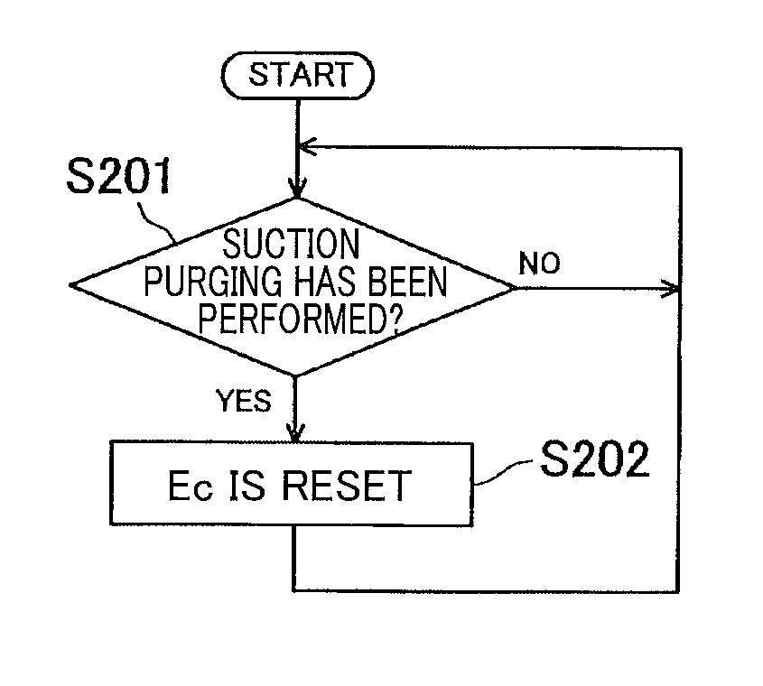
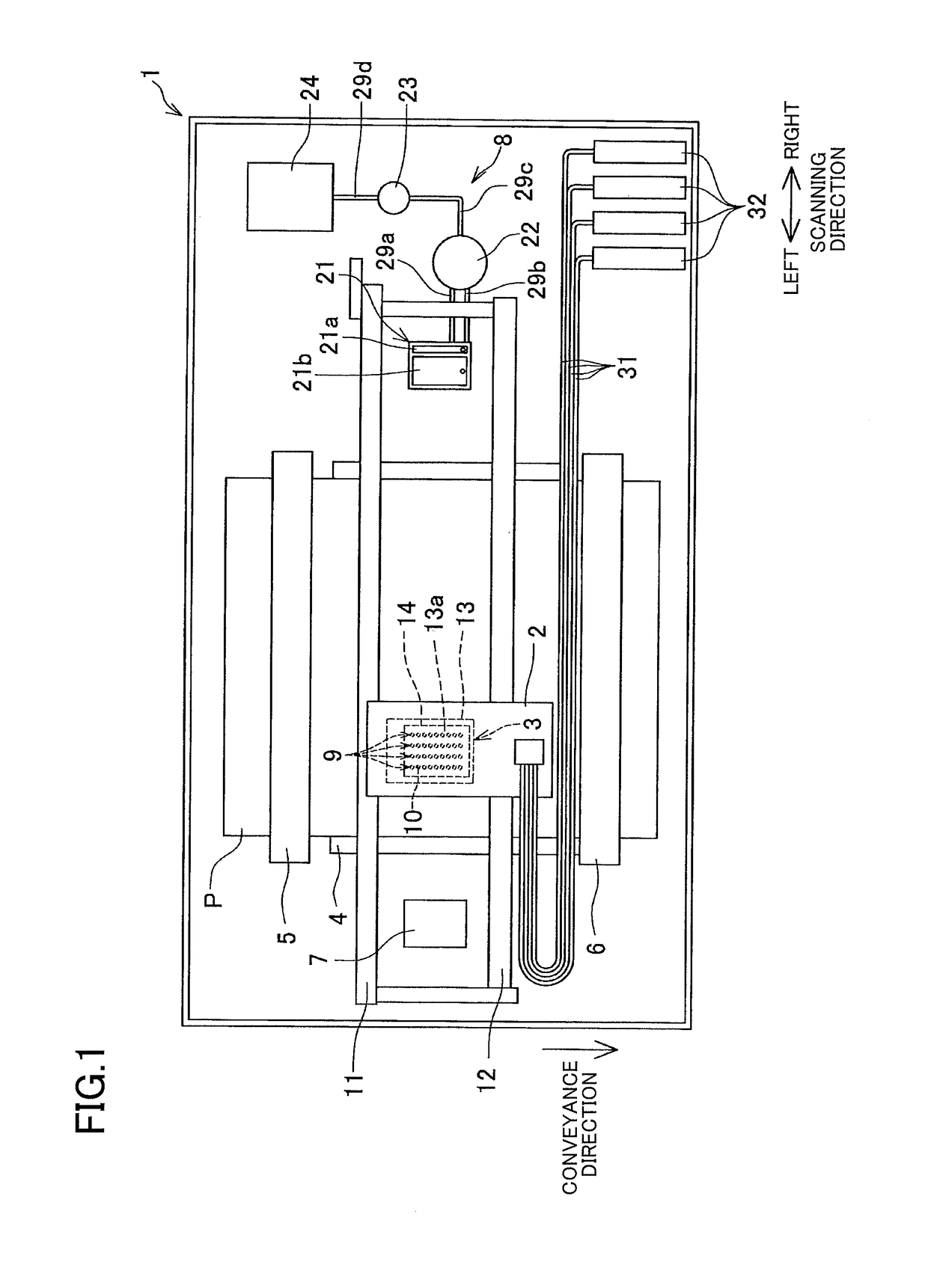
[0063]Next, there will be explained a second embodiment. While the second embodiment relates to the printer 1 according to the first embodiment, the second embodiment differs from the first embodiment in the control by the controller 50. Hereinafter, the control of the controller 50 will be mainly explained.

[0064]As explained in the first embodiment, in the uncapping state, water included in the ink in the cap portions 21a, 21b evaporates, and the cap evaporation rate is accordingly increased. Further, with an increase in the length of time of the uncapping state, evaporation of water included in the ink in the cap portions 21a, 21b proceeds, namely, an increase in the cap evaporation rate is accelerated. In the capping state, water included in the ink in the nozzles 10 moves to the ink in the cap portions 21a, 21b, so that the cap evaporation rate is decreased while the nozzle evaporation rate is increased, namely, the ink in the nozzles 10 becomes thickened. With an increase in th...

third embodiment

[0093]There will be next explained a third embodiment. The third embodiment differs from the second embodiment in the processing for calculating the nozzle evaporation rate Cn[t] and the cap evaporation rate Cc[t].

[0094]In the third embodiment, an inside of the nozzle 10 and an inside of the cap portion 21a, 21b are divided into a plurality of regions arranged in the up-down direction, as shown in FIG. 9. The nozzle evaporation rate Cn[t] and the cap evaporation rate Cc[t] are calculated as explained below in consideration of a movement of water among the regions. The following explanation is made based on an example in which the inside of the nozzle 10 is divided into the number I of nozzle regions Rn[i] (i=1, 2, 3, . . . , I), and the inside of the cap portion 21a, 21b is divided into the number J of cap regions Rc[j] (j=1, 2, 3, . . . , J). In the example below, the ink is present in the cap regions Rc[j] in which j is equal to or larger than J1 (J11 (J1


PUM


Abstract

A liquid ejection apparatus, including: a head having nozzles; a cap to cover the nozzles; a pump fluidically connected to the cap; a switcher for switching a state of the cap between a capping state and an uncapping state, and a controller configured to: determine a cap parameter relating to a cap evaporation rate being an evaporation rate of water in a remaining liquid remaining in the cap, in consideration of (i) an amount of water that moves from the liquid in the nozzles to the remaining liquid in the capping state and (ii) an amount of water that evaporates from the remaining liquid in the uncapping state; and control the head based on the determined cap parameter to perform a flushing for discharging the liquid from the nozzles.

Description

CROSS REFERENCE TO RELATED APPLICATION[0001]The present application claims priority from Japanese Patent Application No. 2017-016335, which was filed on Jan. 31, 2017, the disclosure of which is herein incorporated by reference in its entirety.BACKGROUNDTechnical Field[0002]The following disclosure relates to a liquid ejection apparatus configured to eject a liquid from nozzles.Description of Related Art[0003]As one example of a liquid ejection apparatus configured to eject a liquid from nozzles, there is known a printer configured to eject ink from nozzles. The known printer performs a discharge processing (flushing) for discharging ink from the nozzles to a cap. In the printer, the nozzles are covered by the cap in a standby state in which printing is not performed, so as to prevent or reduce an increase in the viscosity of ink in the nozzles.SUMMARY[0004]In the printer described above, ink remains in the cap to some extent after the discharge processing has been performed. From t...

Claims


Application Information

Patent Timeline
Patent Type & Authority Applications(United States)
IPC IPC(8): B41J2/165
CPCB41J2/16505B41J2/1652B41J2/16508B41J2/16517B41J2/16523B41J2/16532
Inventor IIDA, SHOTARO
Owner BROTHER KOGYO KK
Why Eureka
Try Eureka