

Electric braking device for vehicle
a technology of electric brakes and braking devices, which is applied in the direction of braking systems, automatic initiations, transportation and packaging, etc., can solve the problems of large impact load on the moment of engagement of both engaged parts, and the length of the supply power amount reduction control from “engagement between both parts” to the moment of engagement, etc., to achieve the effect of large impact load
- Summary
- Abstract
- Description
- Claims
- Application Information
AI Technical Summary
Benefits of technology
Problems solved by technology
Method used
Image

Examples
Embodiment Construction
[0027]An electric braking device for a vehicle according to an embodiment of the present invention will be described below with reference to the accompanying drawings.
(Configuration)
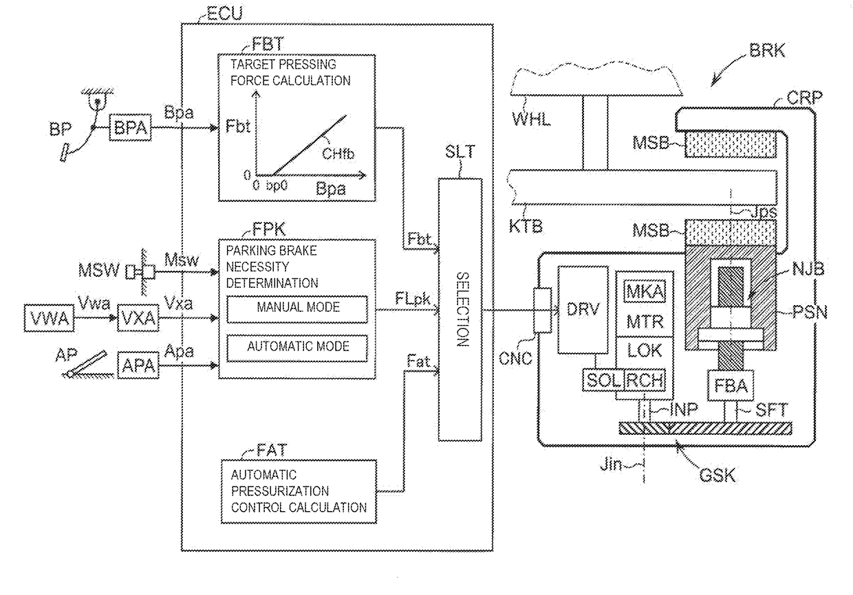
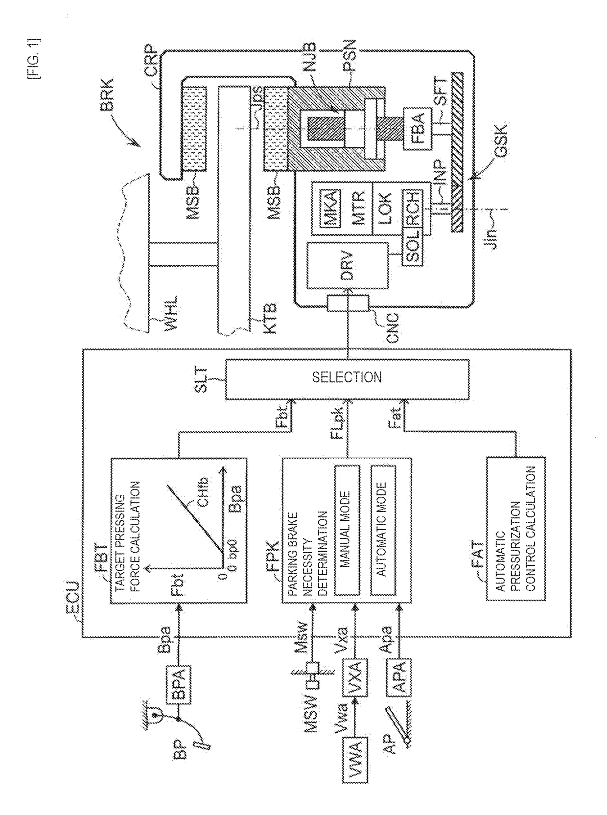
[0028]As shown in FIG. 1, a vehicle having the electric braking device includes a brake operation member BP, an operation amount acquiring means BPA, an acceleration operation member AP, an acceleration operation amount acquiring means APA, a parking brake switch MSW, a wheel speed acquiring means VWA, a vehicle speed acquiring means VXA, an electronic control unit ECU, a braking means (brake actuator) BRK, a rotating member (brake disk) KTB, and a friction member MSB. The electric braking device is disposed for each of the wheels.
[0029]The brake operation member (for example, a brake pedal) BP is a member operated by a driver to decelerate the vehicle. Depending on an operation of the brake operation member BP, braking torques of wheels WHL are adjusted by the braking means BRK. The brake operation amou...
PUM
 Abstract
Description
Claims
Application Information