
Belt drive dual robot gantry

Active Publication Date: 2018-08-02
THE BOEING CO
View PDF7 Cites 3 Cited by
  • Summary
  • Abstract
  • Description
  • Claims
  • Application Information

AI Technical Summary

Benefits of technology

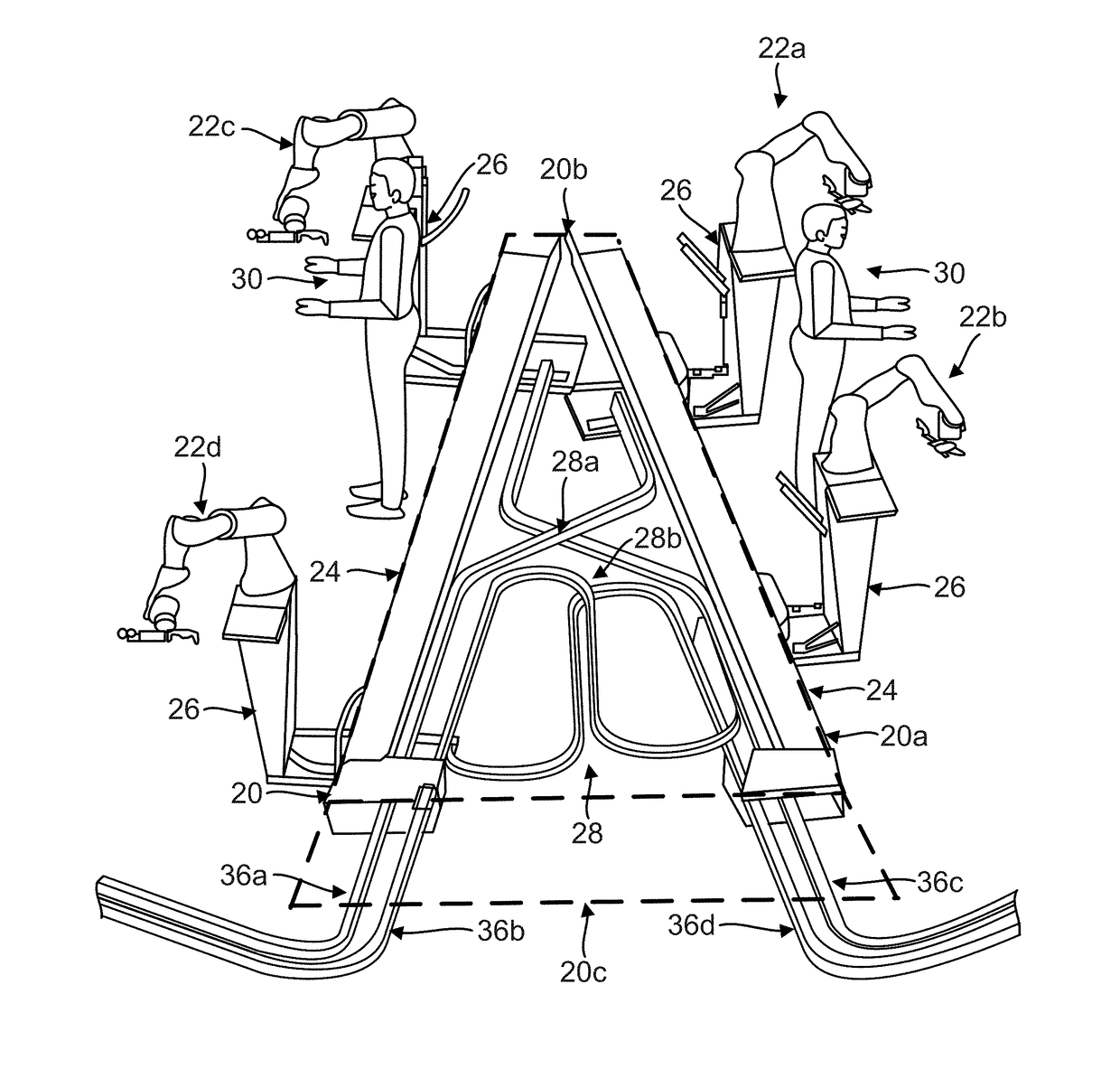
The present patent describes a way to position robots using a gantry. A base platform is provided and a work platform is positioned above it to support humans. The robots are supported on the base platform separately from the work platform. A gantry is positioned above the base platform and near the work platform to support and position the robots along the work platform. This method and apparatus can help to overcome limitations in the prior art and make it easier to position robots in a workplace.

Problems solved by technology

However, platforms used inside the fuselage assembly are not isolated and, as a result, end-of-arm tooling on robots inside the fuselage assembly may bounce or otherwise be impacted due to platform movement caused by human or machine motion nearby, which results in the end-of-arm tooling on the robots being in the wrong location or position.

Method used


Image

  • Belt drive dual robot gantry
  • Belt drive dual robot gantry
  • Belt drive dual robot gantry

Examples


Embodiment Construction

[0025]In the following description, reference is made to the accompanying drawings which form a part hereof, and in which is shown by way of illustration a specific example in which the disclosure may be practiced. It is to be understood that other examples may be utilized and structural changes may be made without departing from the scope of the present disclosure.

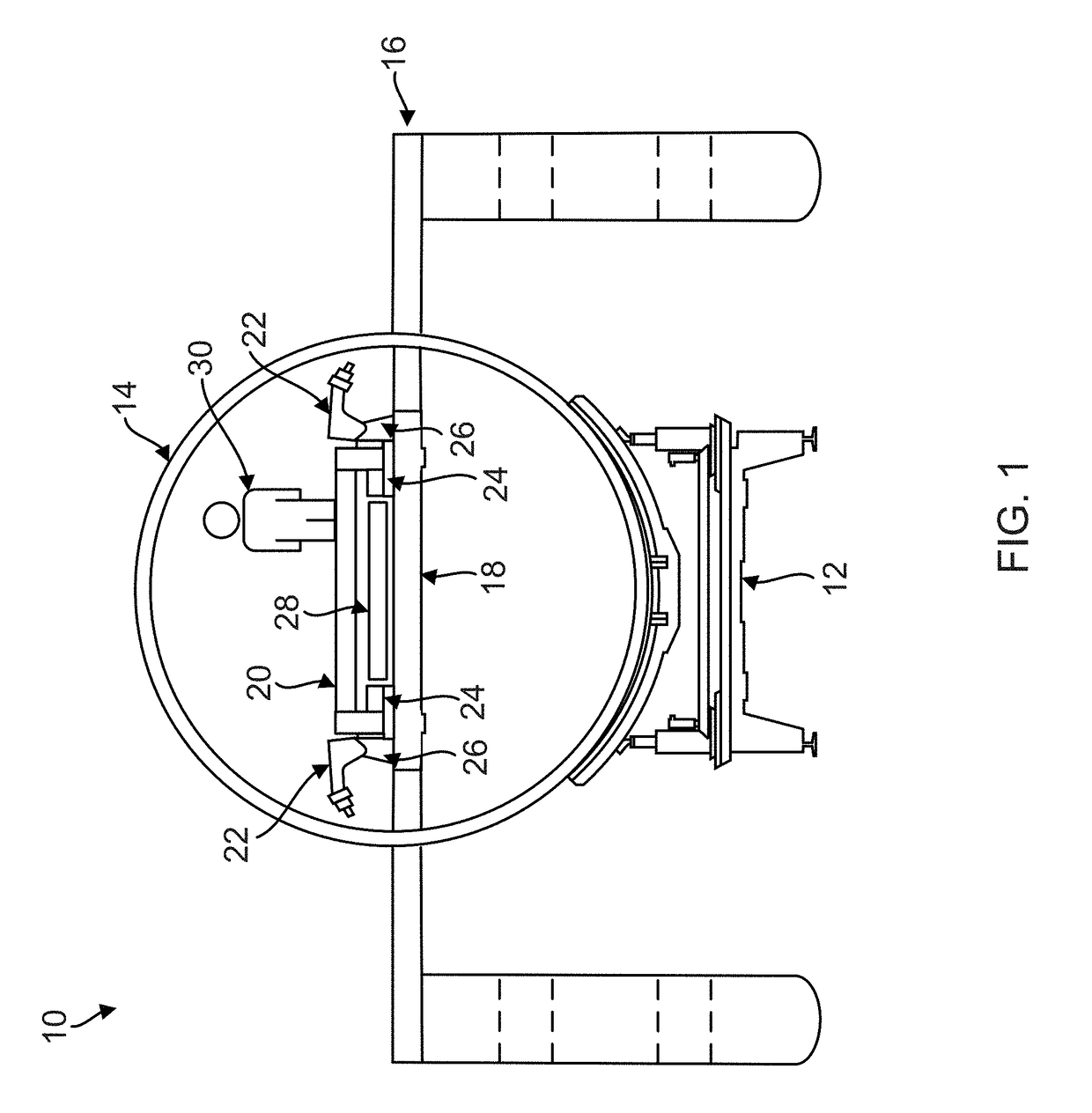
[0026]FIG. 1 illustrates a typical work cell 10 layout that includes one or more cradle fixtures 12 to hold and position a fuselage assembly 14 of an aircraft. Currently, robots are used outside the fuselage assembly 14, and some work inside the fuselage assembly 14 is performed by robots as well. However, it is desired to provide an apparatus for stabilized positioning of collaborative robotics inside the fuselage assembly 14.

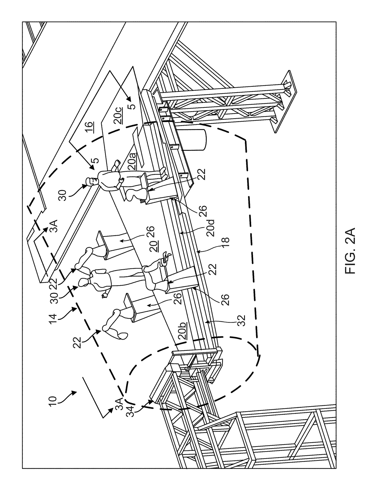
[0027]In this disclosure, the fuselage assembly 14 is positioned adjacent a workstand 16 that includes a base platform 18 positioned inside the fuselage assembly 14. (Some of the support structures ...


PUM


Abstract

A method and apparatus for positioning robots using a gantry. A base platform is provided, and a work platform is positioned above the base platform for supporting one or more humans. One or more robots are supported on the base platform independently of the work platform. At least one gantry is positioned above the base platform and adjacent the work platform for supporting and positioning the robots along the work platform.

Description

CROSS REFERENCE TO RELATED APPLICATIONS[0001]This application is related to the following co-pending and commonly-assigned application:[0002]U.S. Utility application Ser. No. ______, filed on same date herewith, by John Miller and Dennis Mathis, entitled “ISOLATED HUMAN WORK PLATFORM FOR STABILIZED POSITIONING OF COLLABORATIVE ROBOTICS,” docket number 15-2844-US-NP;[0003]U.S. Utility application Ser. No. ______, filed on same date herewith, by John Miller and Dennis Mathis, entitled “CABLE CARRIER CROSSOVER SUPPLYING FOUR NON-STATIC LOCATIONS,” docket number 16-1437-US-NP; and[0004]U.S. Utility application Ser. No. ______, filed on same date herewith, by John Miller and Dennis Mathis, entitled “SYSTEM FOR FOUR COLLABORATIVE ROBOTS AND HUMANS IN A NARROWING WORK ENVELOPE,” docket number 16-1450-US-NP;[0005]all of which applications are incorporated by reference herein.BACKGROUND INFORMATION1. Field[0006]The disclosure is related generally to robotics and more specifically to an isola...

Claims


Application Information

Patent Timeline
IPC IPC(8): B66C19/00
CPCB66C19/005B25H5/00B25J9/10B64F5/10B25J19/00B25J5/02B25J9/0084B25J9/104B25J19/002
Inventor MILLER, JOHN ERICMATHIS, DENNIS R.
Owner THE BOEING CO
Learn More