
A slow-light generating optical device and a method of producing slow light with low losses

Inactive Publication Date: 2018-08-02
UNIVERSITY OF COPENHAGEN
View PDF0 Cites 1 Cited by
  • Summary
  • Abstract
  • Description
  • Claims
  • Application Information

AI Technical Summary

Benefits of technology

The patent describes a new design for a device called a planar waveguide that can create long delays with low loss and without experiencing a phenomenon called Anderson localization. The device uses nanostructures that ensure the modes of light traveling in opposite directions are not affected by each other, reducing the amount of light that is lost during the delay. By modifying the design of the nanostructures, the device can have extended delays while maintaining low loss. The waveguide is designed as a floating structure or on top of a low refractive index material to minimize the loss of light. Overall, this design can create longer delays with significantly less loss and improved performance.

Problems solved by technology

This weak interaction with matter does, however, have its downside; it makes it very difficult to manipulate the properties of a light pulse in such a medium.
This is because the nanophotonic circuits that have been used thus far have considerable scattering losses and have only demonstrated modest delays (500 picoseconds with 7 dB of loss).
Unfortunately, this cannot be realized experimentally as nanometre-scale imperfections inevitably introduced during the fabrication process disturb light propagation causing light to scatter back in the opposite direction or out of the waveguide.
This has so far prevented any commercial application of photonic-crystal waveguides for slow-light devices.
However, the article does not relate to the formation of slow light, and the described waveguides are prone to large backscattering losses due to manufacturing imperfections as explained in the aforementioned paragraph.

Method used


Image

  • A slow-light generating optical device and a method of producing slow light with low losses
  • A slow-light generating optical device and a method of producing slow light with low losses
  • A slow-light generating optical device and a method of producing slow light with low losses

Examples


example i

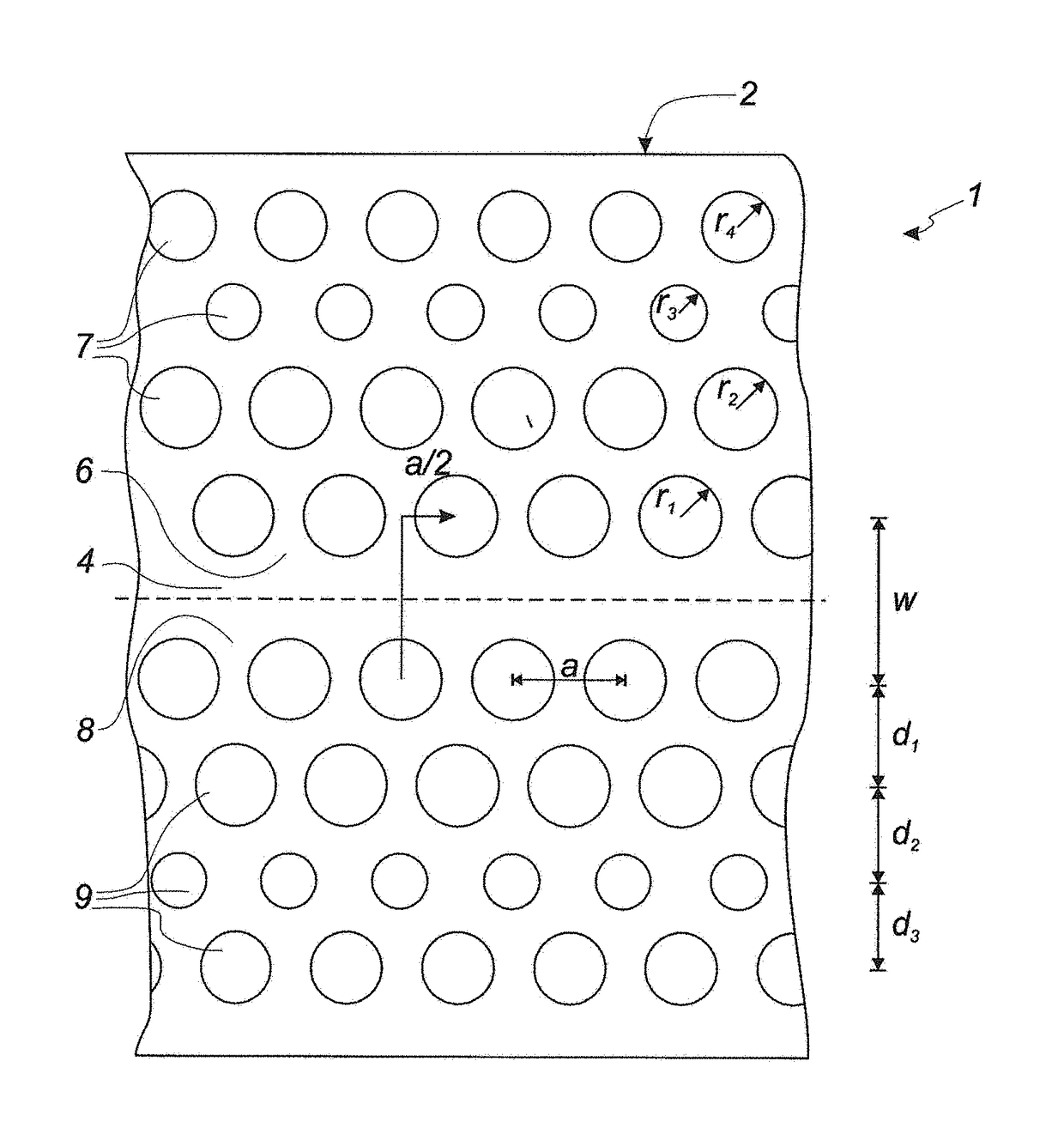
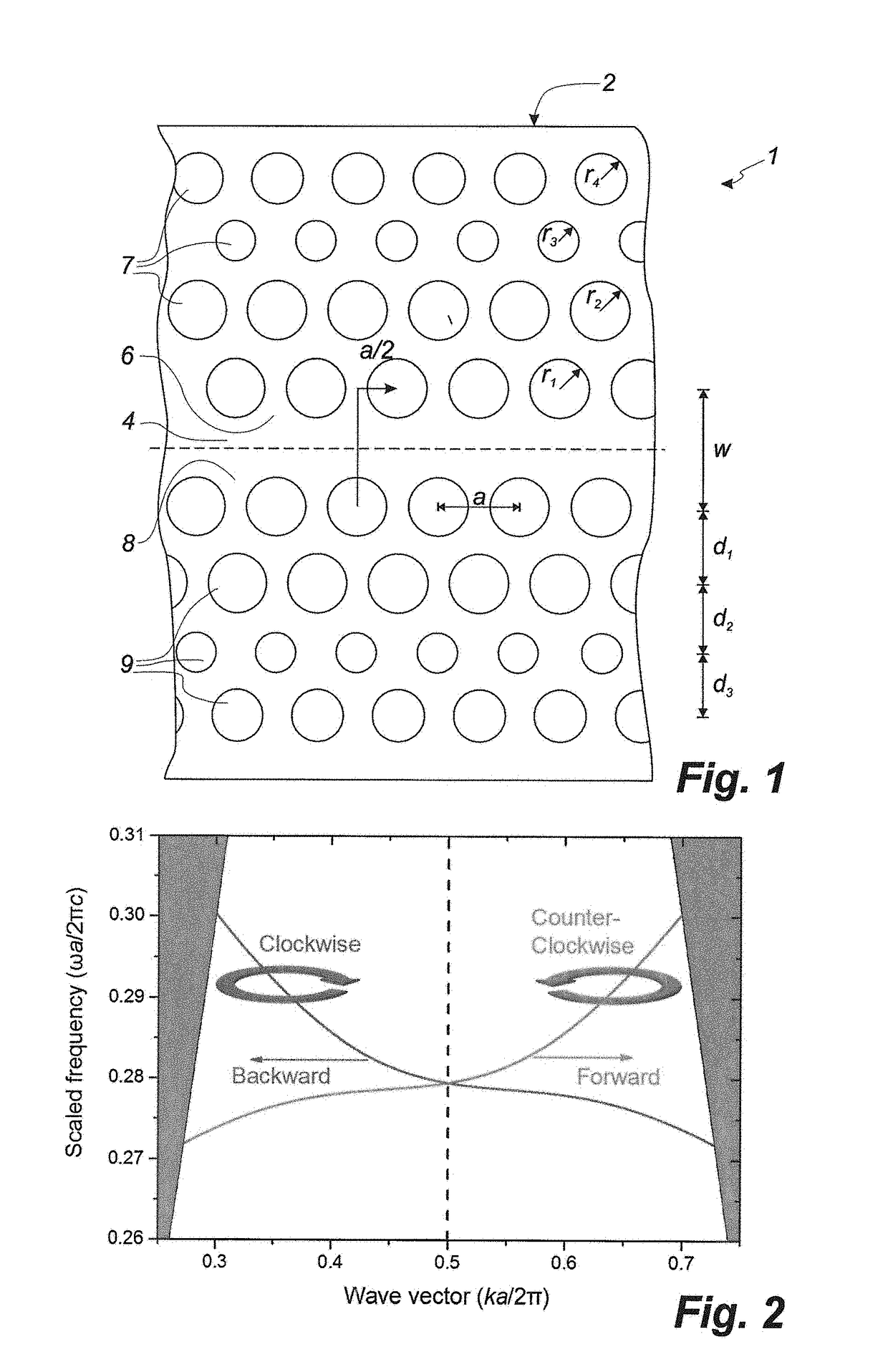
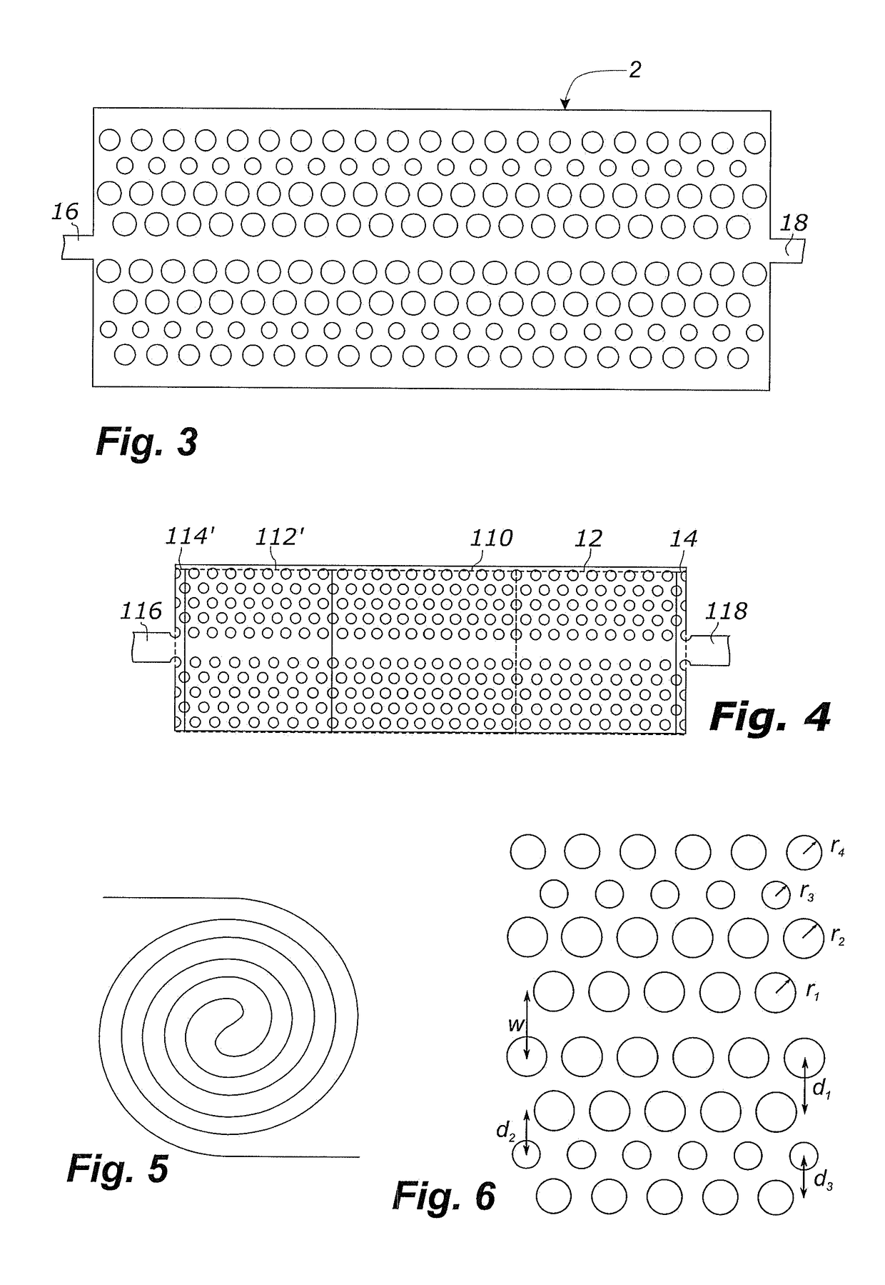
[0085]In the first example, shown in FIG. 6, the planar waveguide is designed with circular holes. The radii of the holes in the first to fourth rows are r1=0.35a, r2=0.35a, r3=0.24a, and r4=0.30a, respectively. The width of the guiding region is w=(0.75√3) a. The distances between adjacent rows are d1=(1.25√3 / 2) a, d2=(0.95√3 / 2) a, and d3=(0.90√3 / 2) a, respectively. The planar waveguide is designed as a membrane having a thickness of 2a / 3. The waveguide exhibits a dispersion curve as shown in FIG. 2.

[0086]The shown planar waveguide is adapted to guide light with a group index, ng, of 39 at the Dirac point. The experiments showed no Anderson localization occurs over a propagation distance of at least 300 micrometres.

example ii

[0087]In the second example, shown in FIG. 7, the planar waveguide is designed with square holes. The sides of the holes in the first to fourth rows have a side length of l1=0.62a, l2=0.62a, l3=0.43a, and l1=0.53a, respectively. The width of the guiding region is w=(0.75√3) a. The distances between adjacent rows are d1=(1.25√3 / 2) a, d2=(0.95√3 / 2) a, and d3=(0.90√3 / 2) a, respectively. The planar waveguide is designed as a membrane having a thickness of 2a / 3. The planar waveguide exhibits a dispersion curve as shown to the right in FIG. 7, where the energy bands of forward propagating mode and the backward propagating are substantially mirror symmetric about the Dirac point.

[0088]The shown planar waveguide is adapted to guide light with a group index, ng, of 42 at the Dirac point.

example iii

[0089]In the third example, shown in FIG. 8, the planar waveguide is designed with holes formed as equilateral triangles with one side facing towards the guiding region and an apex pointing away from the guiding region. The sides of the holes in the first to fourth rows have a side length of l1=0.9a, l2=0.74a, l3=0.81a, and l1=0.75a, respectively. The width of the guiding region is w=(0.91√3) a. The distances between adjacent rows are d1=(1.2√3 / 2) a, d2=(1.1√3 / 2) a, and d3=(0.78√3 / 2) a, respectively. The planar waveguide is designed as a membrane having a thickness of 2a / 3. The planar waveguide exhibits a dispersion curve as shown to the right in FIG. 8, where the energy bands of forward propagating mode and the backward propagating are substantially mirror symmetric about the Dirac point.

[0090]The shown planar waveguide is adapted to guide light with a group index, ng, of 50 at the Dirac point.

[0091]While the invention in the previous embodiments has been described for designs with...


PUM


Abstract

A slow-light generating optical device (1) is disclosed. The optical device comprises a planar waveguide (2), and the planar waveguide comprises: a longitudinal extending guiding region (4) with a first side (6) and a second side (8), a first nanostructure (7) arranged on the first side (6) of the guiding region (4), and a second nanostructure (9) arranged on the second side (7) of the guiding region (4). The planar waveguide (2) includes a first longitudinal region where the first nanostructure (7) and the second structure (9) are arranged substantially glide-plane symmetric about the guiding region (4) of the planar waveguide, and the first and the second nanostructures (7, 9) are designed so that the planar waveguide has a band structure and is adapted to guide a forward propagating mode and a backward propagating mode possessing energy bands, which individually are non-degenerate and mutually degenerate, and which intersect each other and form a Dirac point at a Brillouin zone edge.

Description

FIELD OF THE INVENTION[0001]The present invention relates to a slow-light generating optical device and a method of producing slow light.BACKGROUND OF THE INVENTION[0002]Light travels at 299,792,458 metres per second. This huge speed makes it perfect for telecommunication across different continents. For such applications, it is also fortunate that light interacts only very weakly with the medium within which it travels, and therefore light pulses can travel very long distances in optical fibres before being absorbed or degraded. This weak interaction with matter does, however, have its downside; it makes it very difficult to manipulate the properties of a light pulse in such a medium. Ideally, one would like to be able to propagate light very long distances in a weakly interacting medium and then, when manipulation and control of light are required, propagate in a strongly interacting medium. One strategy for achieving such a strongly interacting medium is to engineer a photonic ma...

Claims


Application Information

Patent Timeline
IPC IPC(8): G02B6/122G02B6/126
CPCG02B6/1225G02B6/126G02F2202/32G02B2006/1213
Inventor STOBBE, SORENMAHMOODIAN, SAHANDLODAHL, PETERFERNANDEZ, PEDRO DAVID GARCIA
Owner UNIVERSITY OF COPENHAGEN
Learn More