
Device, system and method using non ip-based eps bearer

a non-internet protocol and bearer technology, applied in the field of radio access networks, can solve the problems of less computational power, significant amount of bandwidth, and device that swallows network resources, and achieves less communication power, less computational power, and less computational power

Active Publication Date: 2018-08-02
INTEL CORP
View PDF0 Cites 12 Cited by
  • Summary
  • Abstract
  • Description
  • Claims
  • Application Information

AI Technical Summary

Benefits of technology

The patent text discusses a network protocol that reduces communication complexity for low-power devices in cellular networks, particularly in the Internet of Things (IoT). The invention aims to provide a non-IP based EPS bearer that reduces communication complexity for user equipment (UE) while maintaining network access and user experience. The invention also includes methods for establishing and handing over the non-IP EPS bearer, as well as a functional block diagram of a UE. The technical effect of the invention is to provide a more efficient and effective network architecture for low-power devices in cellular networks.

Problems solved by technology

UEs that individually consume significant amounts of bandwidth (through the use of streaming video and other bandwidth-intensive applications) are, however, not the only types of device that swallow network resources.
MTC UEs pose a particular challenge for communication networks and device manufacturers as it is typically desired for such UEs to be low cost and low power, leading to UEs that are less computationally powerful and have less power for communication.
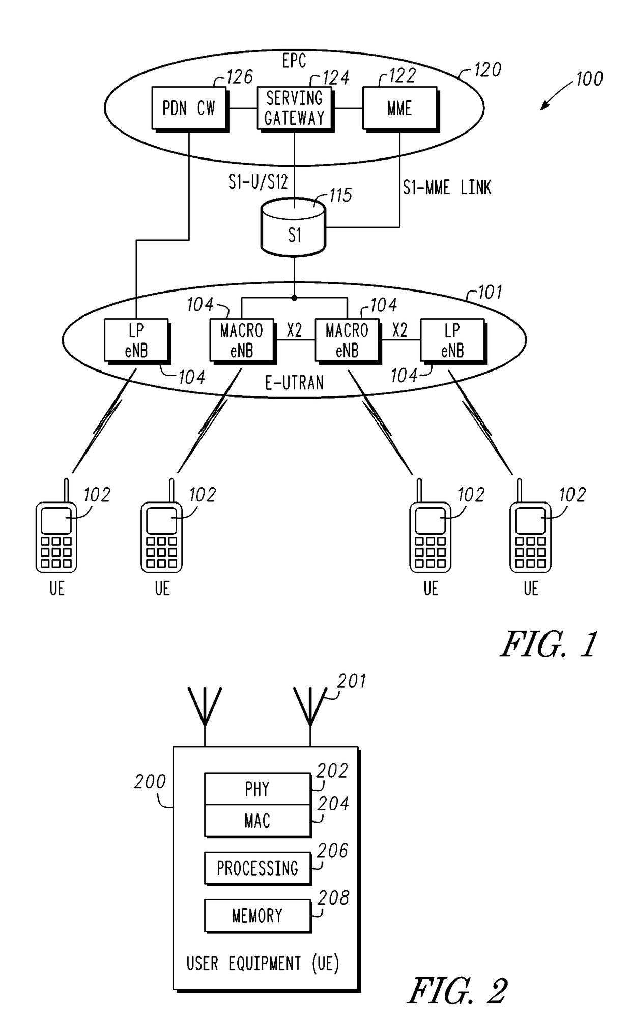
UEs 102 may typically implement Transmission Control Protocol / Internet Protocol (TCP / IP) stacks, increasing the complexity of the UEs and processing provided by the processing circuitry 206 due to the formatting and compression used in the protocol.
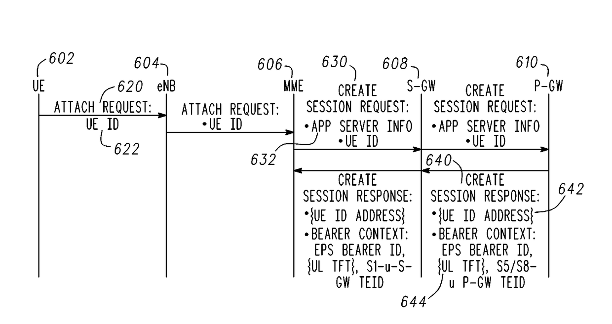
In some embodiments, however, the UE 602 may be mobile and thus may not remain connected to the same eNB at all times. Establishing a NIP bearer for different eNBs may be complicated when the UE ID changes.
However, the Attach Request may not contain the UE ID 722.
Thus, EPS bearer grouping may no longer be possible.
Unfortunately, not all target eNBs may be able to support all types of EPS bearers.

Method used


Image

  • Device, system and method using non ip-based eps bearer
  • Device, system and method using non ip-based eps bearer
  • Device, system and method using non ip-based eps bearer

Examples


example 15

[0113]In Example 15, the subject matter of any one or more of Examples 8-14 optionally include that the processing circuitry is further arranged to: configure the interface to receive the UE ID from the MME in a Create Session Request during an initial attach procedure of the UE and provide the UE ID to the eNB through the MME in an Attach Accept message, the UE ID created in the MME without having been provided from the eNB in an Attach Request from the eNB.

[0114]In Example 16, the subject matter of any one or more of Examples 8-15 optionally include that the processing circuitry is further arranged to: generate the UE ID such that the UE ID originates at the P-GW, and configure the interface to transmit the UE ID to the MME in a Create Session Response.

[0115]In Example 17, the subject matter of any one or more of Examples 6-16 optionally include that: the processing circuitry is further arranged to configure the interface to participate in an initial attach procedure of the UE, a ...


PUM


Abstract

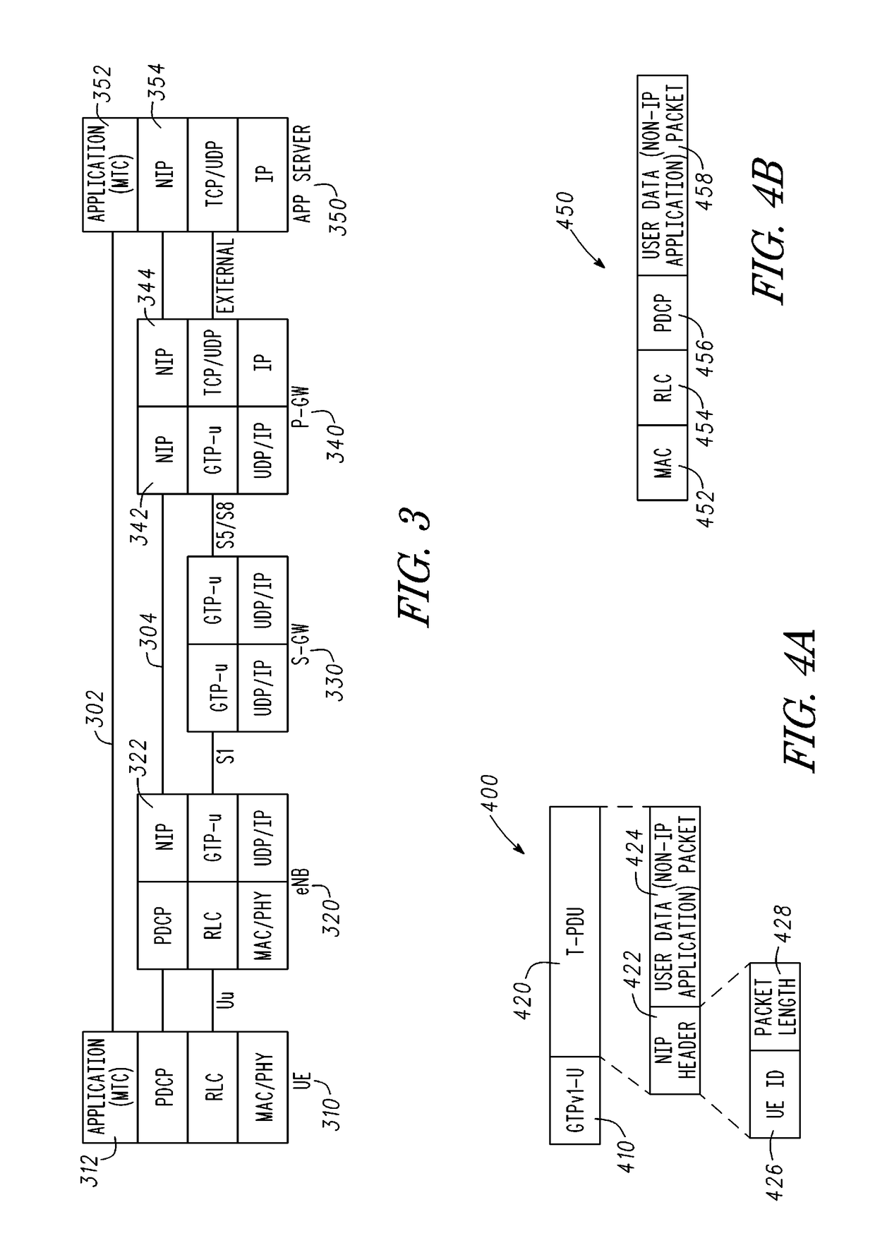
Devices and methods of using a reduced complexity network protocol are generally described. An evolved NodeB (eNB) transmits an Attach Request to a mobility management entity (MME), which transmits a Create Session Request for transmission of non-IP (NIP) data of user equipment (UE) to a Packet Data Network (P-GW). The P-GW in response transmits a Create Session Response, with the UE ID if originating at the P-GW and free from a UE IP address and an Up Link Traffic Flow Template, to the MME, which transmits an Attach Accept to the eNB and UE. A UE identifier (UE ID) either originates at the UE and is transmitted in the Attach Request, or is generated by the eNB, MME or P-GW. The NIP data has a tunneling NIP data packet with a NIP header with the UE ID and a NIP user data packet free from TCP / IP encapsulation and header compression.

Description

PRIORITY CLAIM[0001]This application claims the benefit of priority to U.S. Provisional Patent Application Ser. No. 62 / 199,553, filed, Jul. 31, 2015, and entitled “DEVICE, SYSTEM AND METHOD USING NON IP-BASED EPS BEARER,” which is incorporated herein by reference in its entirety.TECHNICAL FIELD[0002]Embodiments pertain to radio access networks. Some embodiments relate to Non-Internet Protocol (Non-IP) bearer communications in cellular networks, including Third Generation Partnership Project Long Term Evolution (3GPP LTE) networks and LTE advanced (LTE-A) networks as well as tth generation (4G) networks and 5th generation (5G) networks.BACKGROUND[0003]Use of Third Generation Long Term Evolution (3GPP LTE) systems and LTE advanced (LTE-A) networks continues to increase quickly. In part this may be due to the penetration of user equipment (UE) such as smartphones and other data-intensive devices and applications into all parts of modern life. UEs that individually consume significant a...

Claims


Application Information

Patent Timeline
IPC IPC(8): H04W76/12H04W4/70H04W76/11H04W48/20
CPCH04W76/12H04W4/70H04W76/11H04W48/20H04W80/06H04W80/04H04W60/00H04W40/02H04W28/0215H04L45/306H04W8/26H04W36/08H04L69/16Y02D30/70H04W28/06H04L69/00
Inventor ZHU, JINGJHA, SATISH CHANDRAVANNITHAMBY, RATHRASHID, MOHAMMAD MAMUNURGUPTA HYDE, MARUTISIVANESAN, KATHIRVETPILLAI
Owner INTEL CORP
Learn More