Lift rotor and vertical or short take-off and/or landing hybrid aerodyne comprising same

a technology of lift rotor and hybrid aerodyne, which is applied in the direction of vertical landing/take-off aircraft, rotocraft, vehicles, etc., can solve the problems of uncompetitive concept, mechanical complexity and fragile design, and none of those systems have seen genuine development and commercialization, so as to simplify the pitch adjustment mechanism and not be widely used. , the effect of providing li

Active Publication Date: 2018-08-09
INNOSTAR
View PDF3 Cites 21 Cited by
  • Summary
  • Abstract
  • Description
  • Claims
  • Application Information

AI Technical Summary

Benefits of technology

[0016]Finally, it is possible to use two single-blades rotating in opposite directions, i.e. contrarotating blades. For example, helicopters of the Kamov type make use of contrarotating rotors. Despite the advantages offered by this type of contrarotating concept, the complexity of simultaneously controlling both collective pitch and also cyclic pitch at two levels along the axis of the rotor while using a contrarotating rotor means that this design is mechanically complex and fragile, and is therefore not in widespread use.
[0017]The invention proposed by the Applicants solves those contradictions and makes it possible to propose an overall design for a rotor or rotor system that can simultaneously provide lift effectively during stabilized flight, and that can also be stopped and then put back into rotation completely safely during or after cruising flight at high speed.
[0021]Collective pitch variation: the pitch of the blades can be changed in collective manner only, thereby greatly simplifying the pitch adjustment mechanism. The absence of cyclic pitch variation is compensated by the presence of attitude fans, e.g. at the end of the fuselage and / or of the wings of the fixed wing of the aerodyne, which attitude fans enable the roll and the pitching of the aerodyne to be corrected.
[0026]The single-blades present asymmetrical aerodynamic profiles in their central portions over the so-called “rigid” portions, thereby greatly facilitating restarting the rotor in flight (or putting it back into rotation), and making it possible to “off-load” the driving power applied to the rotor with the help of “natural” drive associated with the forces of the “relative airflow” on the rotor, during (horizontal) movement of the aerodyne in cruising flight.
[0034]the assembly constituted by the active blade and the rigid portion carrying the active blade being hinged about a transverse axis perpendicular to the axis of rotation of the rotor, substantially at said axis of rotation of the rotor mast, and the longitudinal axis of said active blade and of said rigid portion carrying the active blade intersects said axis of rotation, the rotor being characterized in that it comprises at least two substantially identical single-blades rotating in opposite directions, each about a respective one of axes of rotation that are longitudinally spaced apart along the roll axis of the aerodyne, or that are contrarotating about a common axis of rotation of the rotor mast, and in that, during cruising flight, each single-blade is stopped and locked longitudinally in such a manner that the counterweight is oriented towards the front of the aerodyne and the active blade is oriented towards the rear of the aerodyne, substantially in the direction of the roll axis of the aerodyne, and that, during vertical flight, the at least two single-blades rotate in opposite directions at the same angular speed from an initial zero position, which is said longitudinally stopped position.
[0057]at least one single-blade has two active blades carried by the same rigid portion and spaced apart from each other in a V-configuration having an angle of at least 30°, lying substantially in the plane of the corresponding rotor disk.

Problems solved by technology

None of those systems has seen genuine development and commercialization.
It is also possible to increase the number of rotors with blades that are stiff and short in length, but the complexity of power transmission then makes such a concept uncompetitive.Finally, it is possible to use two single-blades rotating in opposite directions, i.e. contrarotating blades.
Despite the advantages offered by this type of contrarotating concept, the complexity of simultaneously controlling both collective pitch and also cyclic pitch at two levels along the axis of the rotor while using a contrarotating rotor means that this design is mechanically complex and fragile, and is therefore not in widespread use.

Method used


Image

  • Lift rotor and vertical or short take-off and/or landing hybrid aerodyne comprising same
  • Lift rotor and vertical or short take-off and/or landing hybrid aerodyne comprising same
  • Lift rotor and vertical or short take-off and/or landing hybrid aerodyne comprising same

Examples


Embodiment Construction

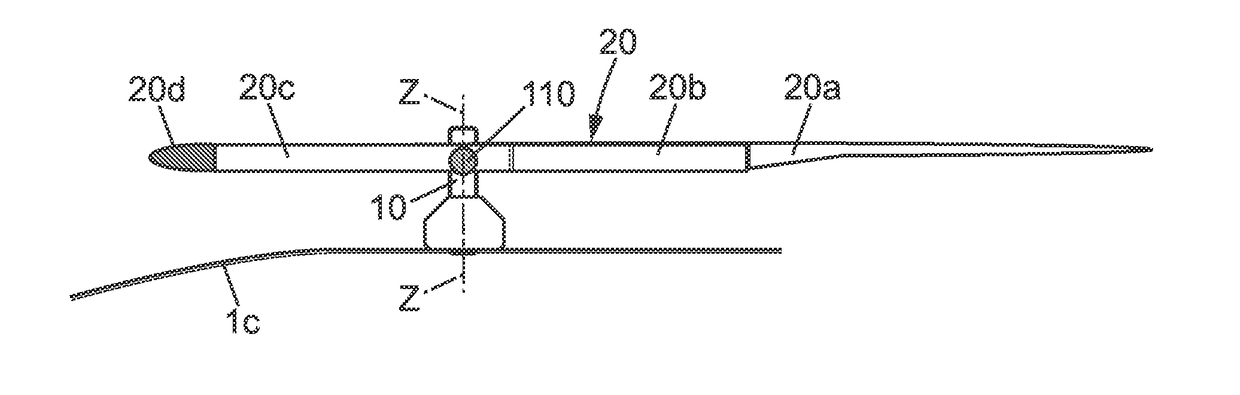
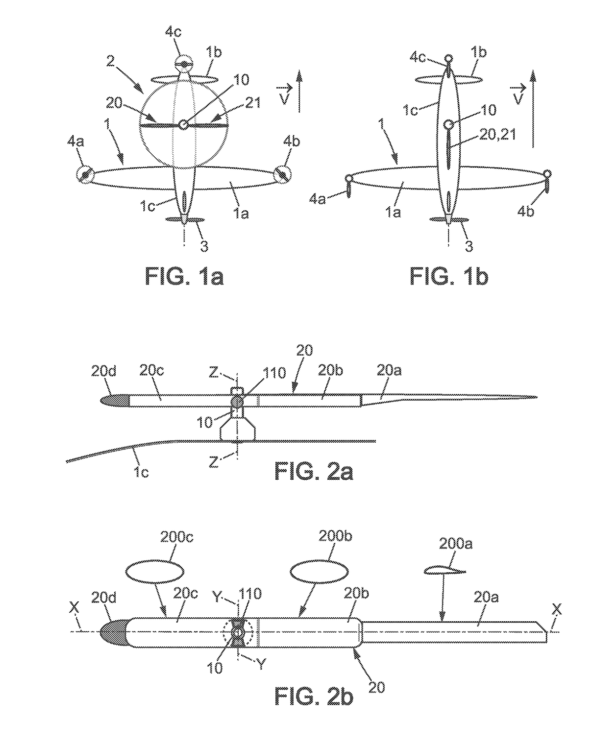
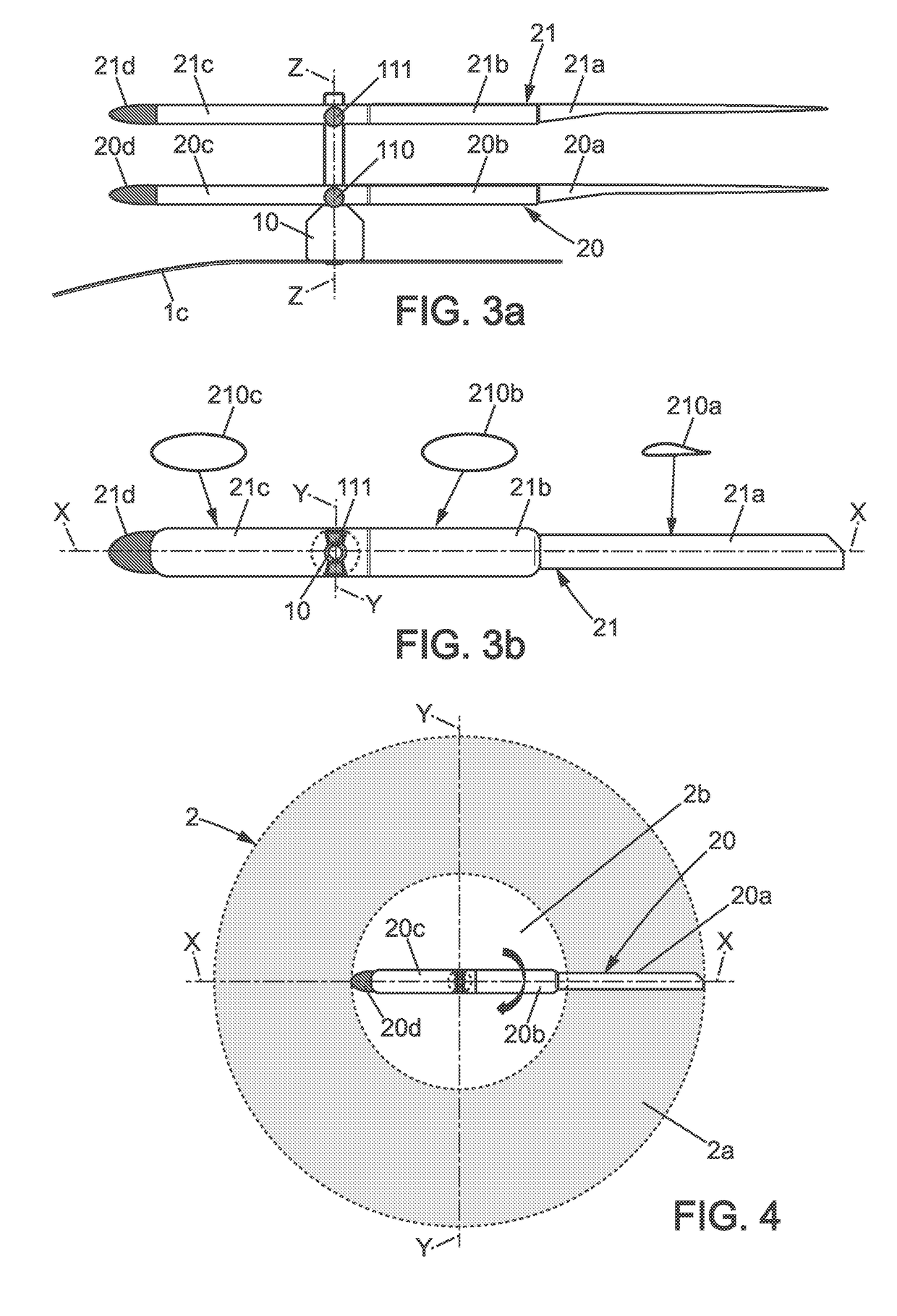
[0080]Throughout the description below, the same numerical or alphanumerical references are used to designate elements that are identical or analogous in the various embodiments shown in the figures, and apart from the portion of the description given with reference to FIGS. 1a, 1b, 9, 16a, and 16b, the device described is solely the rotor system of the aerodyne for providing vertical lift. Except with reference to FIG. 9, no detailed description is given specifically of the power plant, or of the transmission of power from the power plant to the propeller(s), or of the fuselage for carrying passengers and / or a cargo.

[0081]In all of the figures showing one or more single-blades locked in a stationary position, in “horizontal” cruising flight, the longitudinal axis X of a single-blade is an axis parallel to the roll axis or is the roll axis, going towards the front of the aerodyne, and thus in the travel direction of the aerodyne in horizontal flight, and more generally, apart from s...


PUM


Abstract

The rotor of a hybrid aerodyne for producing lift by rotating during a stage of vertical flight and then for being held stationary and stored longitudinally during a stage of cruising flight has at least one single-blade with a counterweight. The length of the active blade that generates lift of the rotor while rotating is significantly shorter than the length of the radius of the rotor. The portion that carries the active blade that makes the connection between the active blade and rotor mast is structurally rigid. The rigid portion that carries the active blade presents a cross-section optimized to provide zero or almost zero lift and very little aerodynamic drag while the rotor is rotating. The assembly is hinged about a transverse axis perpendicular to the vertical axis of the rotor and substantially on the vertical axis of the rotor mast.

Description

BACKGROUND OF THE INVENTIONField of the Invention[0001]The invention relates to a lift rotor or rotor system for a vertical or short takeoff and / or landing hybrid aerodyne, enabling the aerodyne to take off and / or land vertically or over short distances, and then to move horizontally at high speed, the hybrid aerodyne being of the type fitted with a fixed wing and with a rotary wing that is suitable for being held stationary during cruising flight.[0002]The invention applies in particular to small aerodynes having a relatively short wing span (e.g. 4 meters (m)) traveling at a relatively high speed (e.g. 350 kilometers per hour (km / h)) and for use in coastal surveillance missions or indeed missions for surveillance of railways or roads over long distances, or even medical assistance / evacuation transportation over long distances in zones that are relatively uninhabited, given that aerodynes are capable of taking off from any location and in particular without requiring a specific tak...

Claims


Application Information

Patent Timeline
Patent Type & Authority Applications(United States)
IPC IPC(8): B64C27/473B64C27/00B64C27/20
CPCB64C27/473B64C27/008B64C27/20B64C29/0008B64C27/30B64C27/32
Inventor SIMON
Owner INNOSTAR
Why Eureka
Try Eureka