Thermal energy recovery device

a technology of energy recovery device and thermal energy, which is applied in the direction of safety/regulation device, machine/engine, steam engine plant, etc., can solve the problems of poor lubrication of bearings, reduced rotational speed of the pump, and insufficient lubrication of the bearings of the screw turbine when the device restarts

Inactive Publication Date: 2018-08-09
KOBE STEEL LTD
View PDF4 Cites 0 Cited by
  • Summary
  • Abstract
  • Description
  • Claims
  • Application Information

AI Technical Summary

Problems solved by technology

Such a thermal energy recovery device as described in JP 2012-97725 has a concern that the lubrication of the bearing of the screw turbine may be insufficient when the device restarts after stopping.
Specifically, when the thermal energy recovery device comes into a stop operation, the rotational speed of the pump starts decreasing.
When the accumulation of the working medium of liquid phase then causes the bearing of the screw turbine to be immersed in the working medium of liquid phase, there is a concern of poor lubrication of the bearing when the device restarts (when the screw turbine is driven).
Accordingly, the bearing of the expander is inhibited from being immersed in the working medium of liquid phase and thereby poor lubrication of the bearing is inhibited when the thermal energy recovery device restarts.
Also in the thermal energy recovery device above, poor lubrication of the bearing of the expander is inhibited when the device is driven (starts to operate).
In contrast, in the thermal energy recovery device, since the control unit is arranged to open the liquid draining valve after the pump is stopped, such a trouble as described above is inhibited.

Method used


Image

  • Thermal energy recovery device
  • Thermal energy recovery device
  • Thermal energy recovery device

Examples


first embodiment

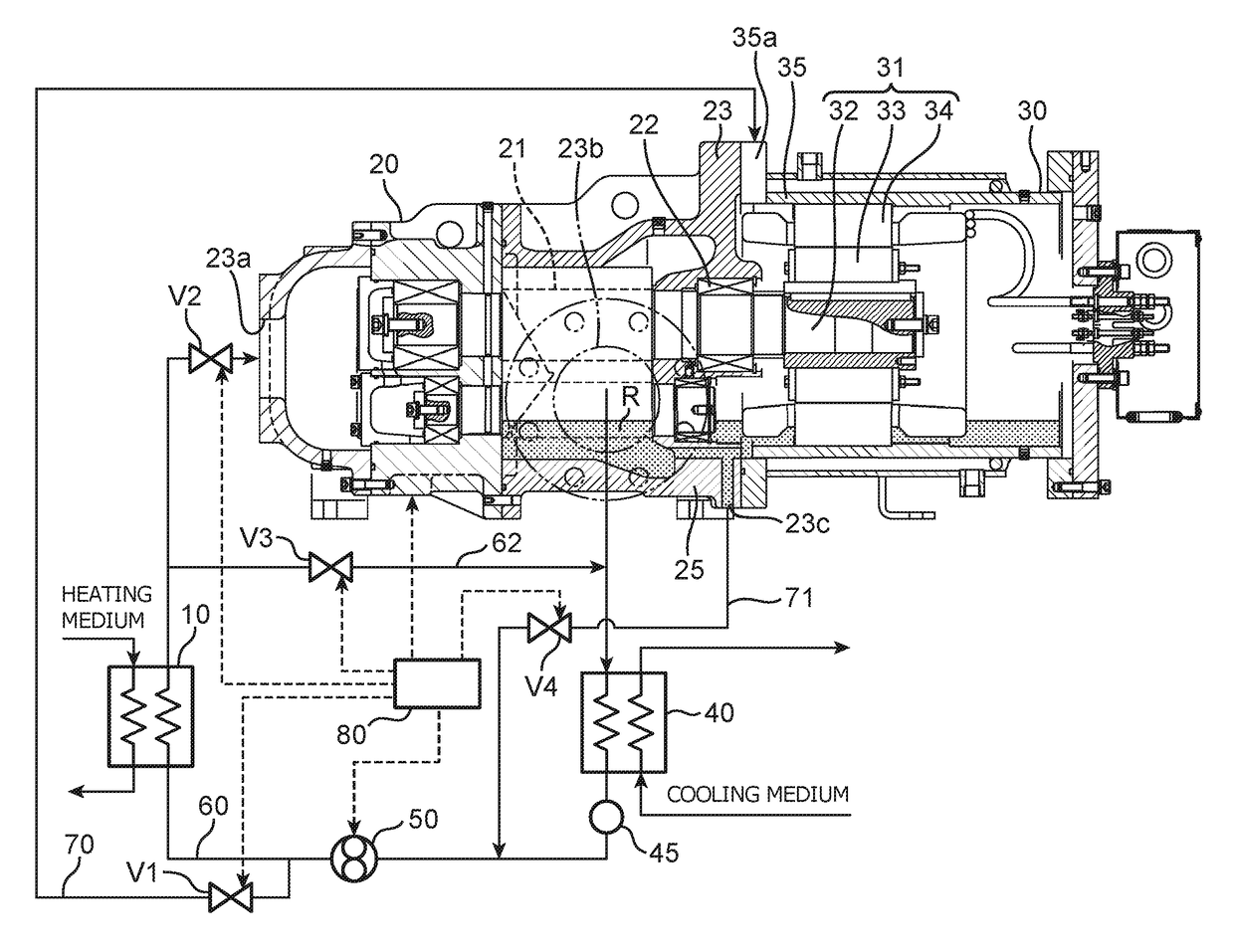
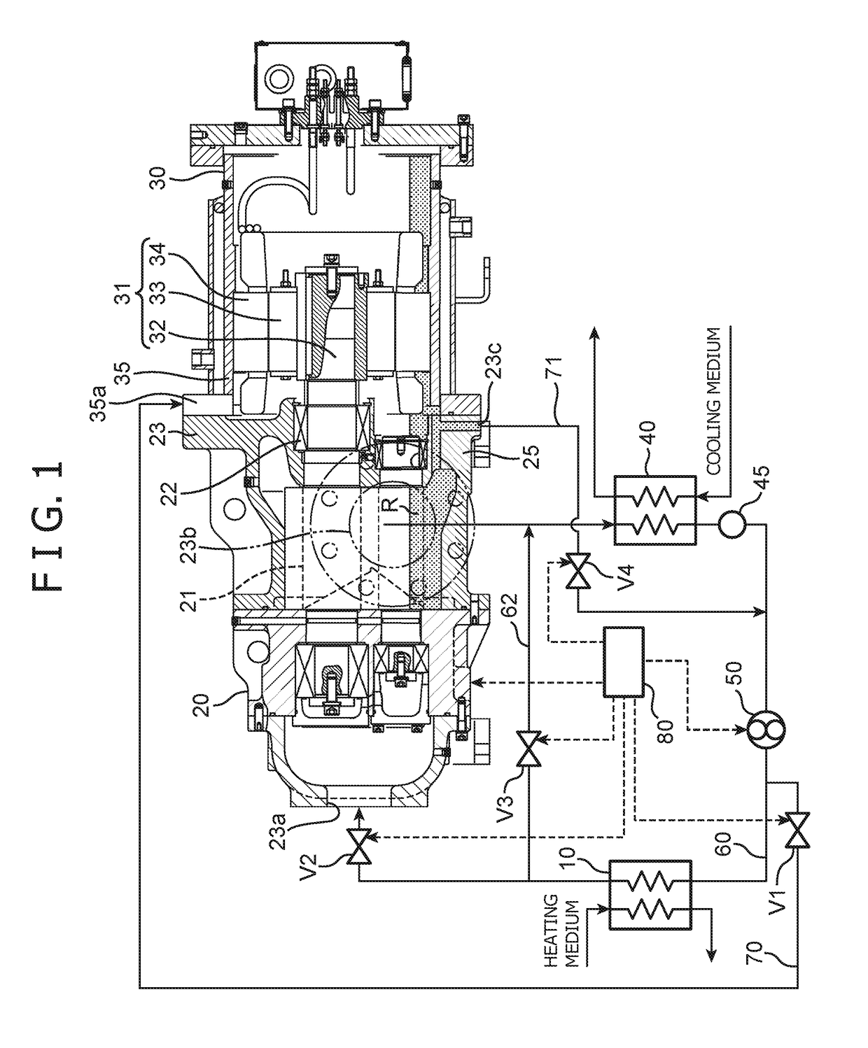
[0024]FIG. 1 shows the configuration of a thermal energy recovery device according to a first embodiment of the present invention. The thermal energy recovery device includes an evaporator 10, an expander 20, a power recovery machine 30, a condenser 40, a pump 50, a circulation flow path 60 connecting the evaporator 10, the expander 20, the condenser 40, and the pump 50 in this order, a cooling flow path 70, and a control unit 80.

[0025]The evaporator 10 evaporates working medium through heat exchange between the working medium and heating medium.

[0026]The expander 20 is provided at a site downstream the evaporator 10 in the circulation flow path 60. The expander 20 expands working medium of gas phase flowing out of the evaporator 10. In this embodiment, the expander 20 employs a volumetric screw expander having a rotor to be rotationally driven by the expansion energy of working medium of gas phase. Specifically, the expander 20 has a pair of male and female screw rotors (rotors) 21...

second embodiment

[0045]Next will be described a thermal energy recovery device according to a second embodiment of the present invention with reference to FIG. 3. It is noted that in the second embodiment, only components different from the first embodiment will be described, and the same structures, operations, and effects as in the first embodiment will not be described.

[0046]In this embodiment, the power recovery machine 30 has a jacket 36, and the downstream end portion of the cooling flow path 70 is connected to the jacket 36.

[0047]The jacket 36 provided in the secondary casing 35 to form a cooling space S that allows working medium of liquid phase to flow between the jacket 36 and the secondary casing 35. The jacket 36 is arranged on the outside of the outer peripheral surface of the secondary casing 35. That is, the cooling space S is formed between the outer peripheral surface of the secondary casing 35 and the inner peripheral surface of the jacket 36. The jacket 36 has an introducing porti...

third embodiment

[0050]Next will be described a thermal energy recovery device according to a third embodiment of the present invention with reference to FIG. 4. It is noted that in the third embodiment, only components different from the first embodiment will be described, and the same structures, operations, and effects as in the first embodiment will not be described.

[0051]While this embodiment shares similarity with the second embodiment in that the power recovery machine 30 has a jacket 36, cooling medium (e.g. cooling water) different from the working medium is supplied to the cooling space S.

[0052]A cooling flow path 73 branched from a cooling medium supply line L1 for supplying cooling medium therethrough is connected to the jacket 36. Accordingly, in this embodiment, cooling medium passing through the cooling space S cools the power recovery unit 31 via the secondary casing 35. Cooling medium that has passed through the cooling space S is returned through a cooling medium recovery flow path...


PUM


Abstract

Provided is a thermal energy recovery device in which poor lubrication of a bearing can be inhibited when an expander is driven. The thermal energy recovery device includes an evaporator (10), an expander (20), a power recovery machine (30), a condenser (40), a pump (50), a circulation flow path (60), a cooling flow path (70) for supplying working fluid from the pump (50) partially to the power recovery machine (30), an on-off valve (V1) provided in the cooling flow path (70), and a control unit (80), in which the expander (20) has a rotor (21), a bearing (22), and a primary casing (23), and in which the power recovery machine (30) has a power recovery unit (31) and a secondary casing (35), and in which upon reception of a stop signal for stopping power recovery by the power recovery machine (30), the control unit (80) closes the on-off valve (V1).

Description

BACKGROUND OF THE INVENTIONField of the Invention[0001]The present invention relates to a thermal energy recovery device.Description of the Related Art[0002]There have conventionally been known thermal energy recovery devices for recovering power from exhaust heat from various types of equipment such as plants. For example, JP 2012-97725 discloses a generator system (thermal energy recovery device) including an evaporator, a closed generator, a condenser, a fluid supply pump, a circulation flow path connecting the evaporator, the closed generator, the condenser, and the fluid supply pump in this order, and a cooling tube. The evaporator evaporates working medium. The closed generator generates electric power from the expansion energy of working medium flowing out of the evaporator. Specifically, the closed generator has a screw turbine for expanding working medium, a generator connected to the screw turbine via an output shaft, and a housing case housing the screw turbine, the outpu...

Claims


Application Information

Patent Timeline
Patent Type & Authority Applications(United States)
IPC IPC(8): F01K13/02F01K23/02
CPCF01K13/02F01K23/02F01D25/12F01K13/00F01C1/16F01C20/06F01C21/02F01C21/04F01C21/06F01C21/001F01D17/145F01D25/16F01K9/02
Inventor ADACHI, SHIGETONARUKAWA, YUTAKANISHIMURA, KAZUMASA
Owner KOBE STEEL LTD
Why Eureka
Try Eureka