Refrigeration apparatus

a technology of refrigerating apparatus and drive shaft, which is applied in the direction of lighting and heating apparatus, positive displacement liquid engine, liquid fuel engine, etc., can solve the problems of variable torque of driving the drive shaft, and consequent pulsating driving current of the electric motor driving the drive sha

Active Publication Date: 2021-04-15
DAIKIN IND LTD
View PDF0 Cites 0 Cited by
  • Summary
  • Abstract
  • Description
  • Claims
  • Application Information

AI Technical Summary

Benefits of technology

[0004]A first aspect of the present disclosure is directed to a refrigeration apparatus. The refrigeration apparatus includes a compressor, a refrigerant circuit with the compressor connected thereto to circulate a refrigerant to perform a refrigeration cycle, and a bearing monitor. The compressor includes a compression mechanism configured to suck and compress a fluid, an electric motor, a drive shaft coupled to the electric motor to drive the compression mechanism, and a plain bearing that supports a journal portion of the drive shaft. The bearing monitor is configured to perform an abnormal-state operation to cope with poor lubrication on the plain bearing if an abnormal state condition indicating that a rate of change of current exceeds a first reference value is satisfied. The rate of change of current is an amount of change in a driving current usable to drive the compressor per unit time. The journal portion of the drive shaft having a surface roughness of at least 0.05 μm. The driving current of the compressor that is normally operating is defined as a rated current. The bearing monitor is configured to calculate the rated current in an operating state of the compressor at a time of determination regarding whether the abnormal state condition is satisfied or not. The bearing monitor is configured to use, as the abnormal state condition, a condition that a value obtained by dividing the rate of change of current by the rated current calculated exceeds a second reference value.

Problems solved by technology

This document shows that damage caused to a bearing of a drive shaft (a crankshaft) driving a compression mechanism by a shortage of lubricant and other factors causes variations in torque for driving the drive shaft, and the driving current of an electric motor driving the drive shaft consequently pulsates.

Method used


Image

  • Refrigeration apparatus
  • Refrigeration apparatus
  • Refrigeration apparatus

Examples


first embodiment

Advantages of First Embodiment

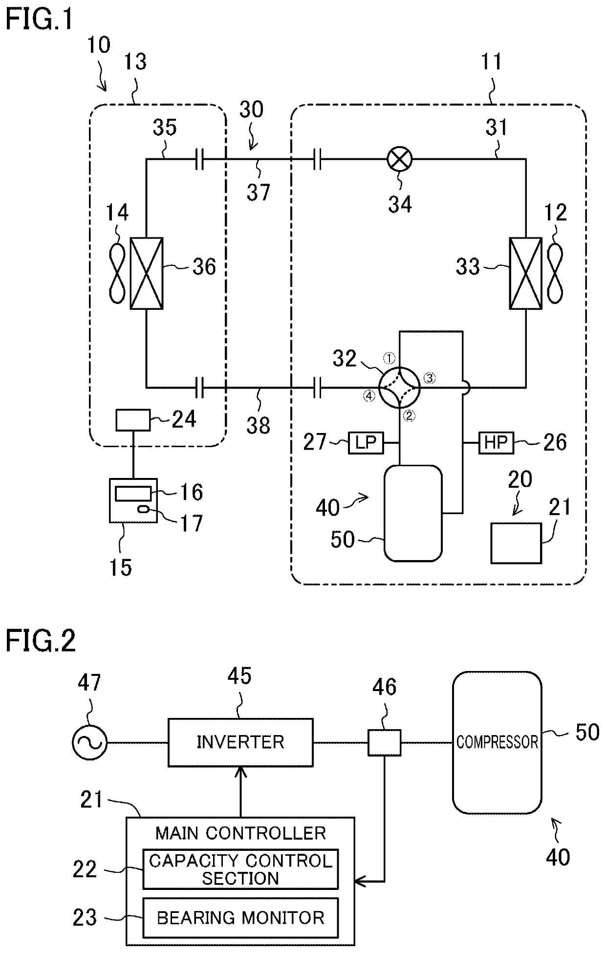
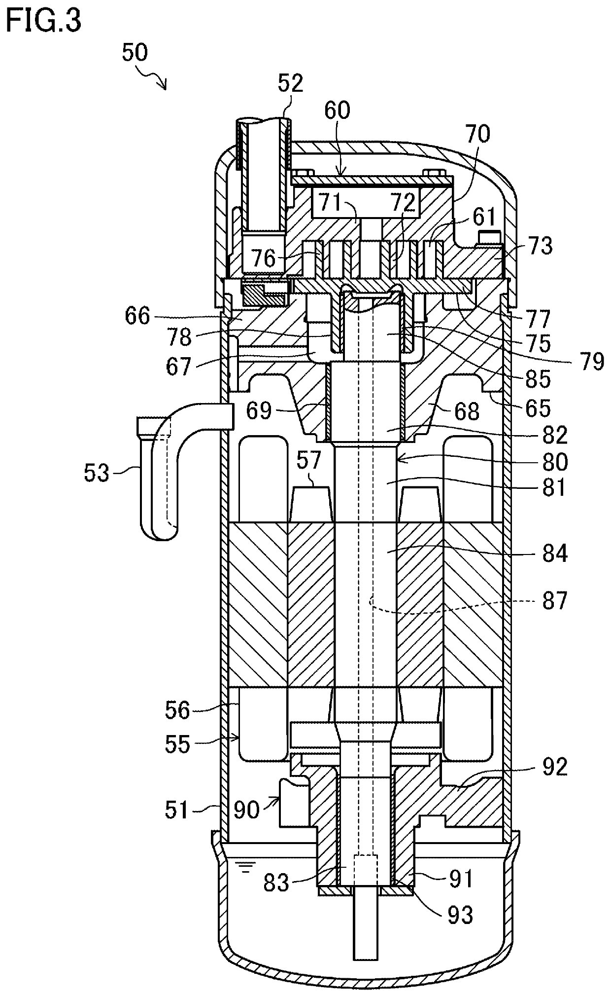
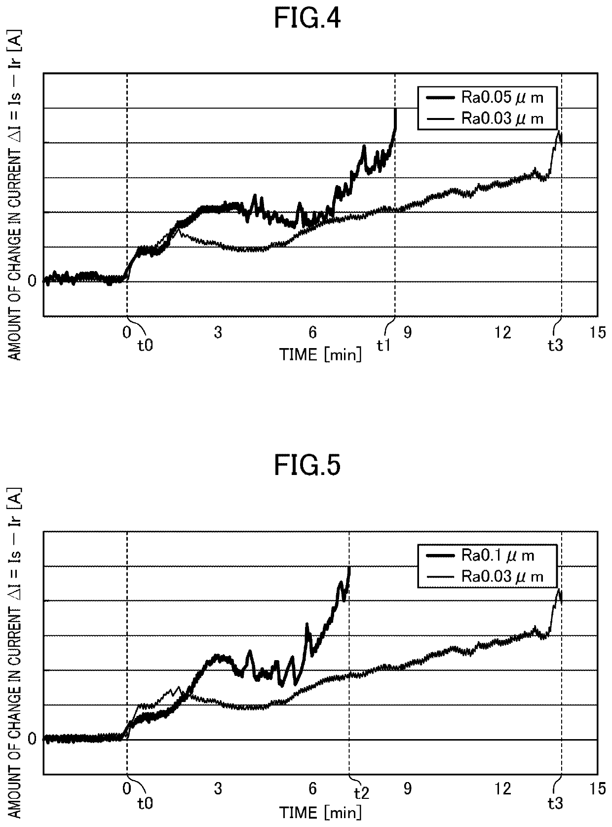
[0076]The compressor unit (40) according to this embodiment includes the compressor (50) and the bearing monitor (23). The compressor (50) includes the compression mechanism (60) configured to suck and compress a fluid, the electric motor (55), the drive shaft (80) that is coupled to the electric motor (55) and drives the compression mechanism (60), and the main bearing portion (68) and the boss (78) serving as plain bearings that respectively support the journal portions (82, 85) of the drive shaft (80). The bearing monitor (23) is configured to perform the abnormal-state operation for coping with poor lubrication on one or both of the main bearing portion (68) and the boss (78) if the abnormal state condition indicating that the rate RI of change of current (which is the amount of change in the driving current for driving the compressor (50) per unit time) has exceeded the first reference value is satisfied. At least the main journal portion (82) and ...

second embodiment

[0089]A second embodiment will be described below. An air conditioner (10) of this embodiment is a modified version of the air conditioner (10) of the first embodiment, in which the configuration of the compressor (50) has been changed. A control system (20) of the air conditioner (10) of this embodiment performs the same operation as that of the control system (20) of the first embodiment. A compressor (50) of this embodiment will now be described.

Compressor

[0090]As shown in FIG. 6, the compressor (50) is a hermetic rotary compressor. The compressor (50) includes a compression mechanism (60), an electric motor (55), and a drive shaft (80), which are housed in a casing (51).

Casing

[0091]The casing (51) is a cylindrical closed container with both ends closed. The casing (51) is arranged so that its axial direction coincides with a vertical direction. The electric motor (55) is arranged above the compression mechanism (60) in the internal space of the casing (51). A suction pipe (52) p...


PUM


Abstract

A refrigeration apparatus includes a compressor connected to a refrigerant circuit, and a bearing monitor. The compressor includes a compression mechanism, an electric motor, a drive shaft, and a plain bearing that supports a journal portion of the drive shaft. The bearing monitor performs an abnormal-state operation to cope with poor lubrication on the plain bearing if an abnormal state condition is satisfied. The abnormal state condition is a condition indicating that a rate of change of current exceeds a first reference value. The rate of change of current is an amount of change in a driving current usable to drive the compressor per unit time. The journal portion of the drive shaft has a surface roughness of at least 0.05 μm.

Description

CROSS-REFERENCE TO RELATED APPLICATIONS[0001]This is a continuation of International Application No. PCT / JP2019 / 022571 filed on Jun. 6, 2019, which claims priority to Japanese Patent Application No. 2018-118566 filed on Jun. 22, 2018. The entire disclosures of these applications are incorporated by reference herein.BACKGROUNDField of Invention[0002]The present disclosure relates to a refrigeration apparatus.Background Information[0003]Brochure of WO 2017 / 042949 discloses an air conditioner including a failure predictor / detector for a compressor. This document shows that damage caused to a bearing of a drive shaft (a crankshaft) driving a compression mechanism by a shortage of lubricant and other factors causes variations in torque for driving the drive shaft, and the driving current of an electric motor driving the drive shaft consequently pulsates. The failure predictor / detector of this document predicts or detects a failure of the compressor based on the amplitude and duration of ...

Claims


Application Information

Patent Timeline
Patent Type & Authority Applications(United States)
IPC IPC(8): F25B31/00F16C33/66
CPCF25B31/002F16C2360/00F16C2233/00F16C33/6681F04B49/10F04B39/0094F04B49/06F04B49/065F04B2203/0201F04C28/28F04C18/0215F04C18/356F04C29/02F04C2270/80F04C2240/54F04C23/008F04C15/0092
Inventor FURUGAKI, TAKASHITANAKA, MASARU
Owner DAIKIN IND LTD
Why Eureka
Try Eureka