
Pre-swirler for gas turbine

Inactive Publication Date: 2018-08-09
DOOSAN HEAVY IND & CONSTR CO LTD
View PDF7 Cites 4 Cited by
  • Summary
  • Abstract
  • Description
  • Claims
  • Application Information

AI Technical Summary

Benefits of technology

This patent aims to make the temperature of a fluid supplied to a blade more stable by increasing the speed of the cooling air that moves through a pre-swirler in a gas turbine.

Problems solved by technology

In the gas turbine operated as described above, transporting cooling air from an air gap at which an inside of the stator is fixed to a rotor assembly to disperse the cooling air to an inner side of the rotor blade is an important problem.
When an amount of air is too small, the turbine blade is overheated, but when air is excessively supplied, combustion efficiency deteriorates.
The swirler used as described above has a problem that a flow rate, pressure, and temperature required by the turbine are not stably satisfied.

Method used


Image

  • Pre-swirler for gas turbine
  • Pre-swirler for gas turbine
  • Pre-swirler for gas turbine

Examples


Embodiment Construction

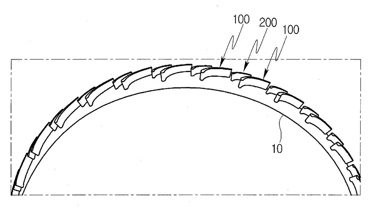
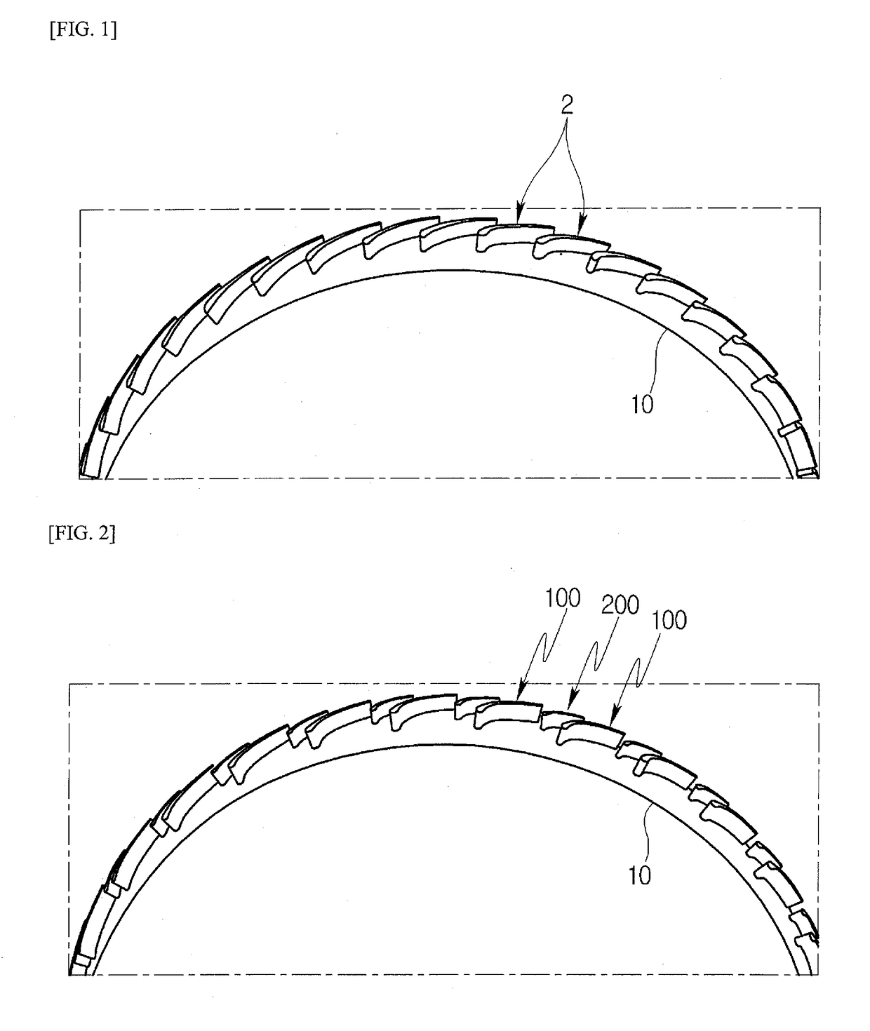
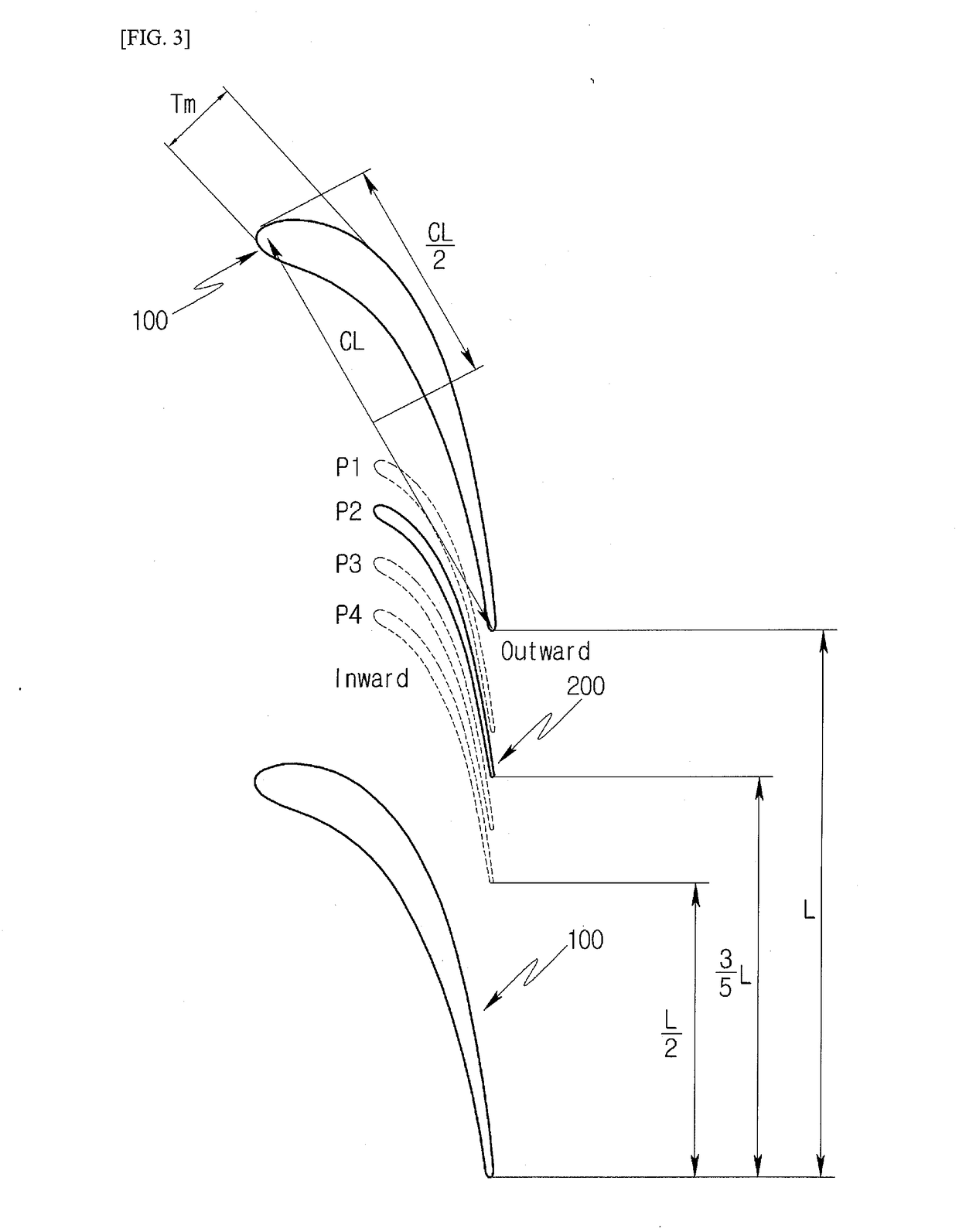
[0046]A pre-swirler for a gas turbine according to an embodiment of the present invention will be described with reference to the accompanying drawings. FIG. 2 is a perspective view illustrating a pre-swirler for a gas turbine according to an embodiment of the present invention, FIG. 3 is a diagram illustrating a main vane and an auxiliary vane according to an embodiment of the present invention, and FIGS. 4 and 5 are diagrams illustrating main vanes according to an embodiment of the present invention.

[0047]Referring to FIGS. 2 to 5, the pre-swirler for a gas turbine according to a present embodiment is configured as a dual vane type. For example, the pre-swirler for a gas turbine includes a plurality of main vanes 100 spaced apart from each other at a predetermined interval along a circumferential direction of a pre-swirler housing 10 provided in a compressor of the gas turbine, and an auxiliary vane 200 disposed between the main vanes 100 spaced apart from each other and having a ...


PUM


Abstract

Disclosed is a pre-swirler for a gas turbine. A pre-swirler for a gas turbine according to an embodiment of the present invention including an auxiliary vane between main vanes disposed along a circumferential direction of a pre-swirler housing of a gas turbine to promote stable movement of cooling air.

Description

CROSS-REFERENCE TO RELATED APPLICATION(S)[0001]This application claims priority to Korean Patent Application No. 10-2017-0016989, filed on Feb. 7, 2017 the disclosure of which is incorporated herein by reference in its entirety.BACKGROUND OF THE INVENTIONField of the Invention[0002]Exemplary embodiments of the present invention relate to a pre-swirler, and more particularly, to a pre-swirler for a gas turbine, including an auxiliary vane between main vanes disposed along a circumferential direction of a pre-swirler housing of a gas turbine to promote stable movement of cooling air.Description of the Related Art[0003]In general, as fuel is combusted in a combustion chamber, high temperature combustion gas is generated in a gas turbine. The high-temperature and high-pressure gas expands while flowing along a stator vane row and a turbine rotor blade row that are alternately disposed in a turbine portion, and available power is generated using energy resulting from the expansion.[0004]...

Claims


Application Information

Patent Timeline
IPC IPC(8): F02C7/18F01D25/12F15D1/00
CPCF02C7/18F01D25/12F15D1/0015F01D5/146F01D9/041F05D2240/301F05D2250/70F05D2260/14F05D2240/35F23R3/14F23R3/26F23R3/42F23R2900/03043
Inventor KIM, DONG HWA
Owner DOOSAN HEAVY IND & CONSTR CO LTD
Learn More